158
Allocations and Setting Table Appendix F
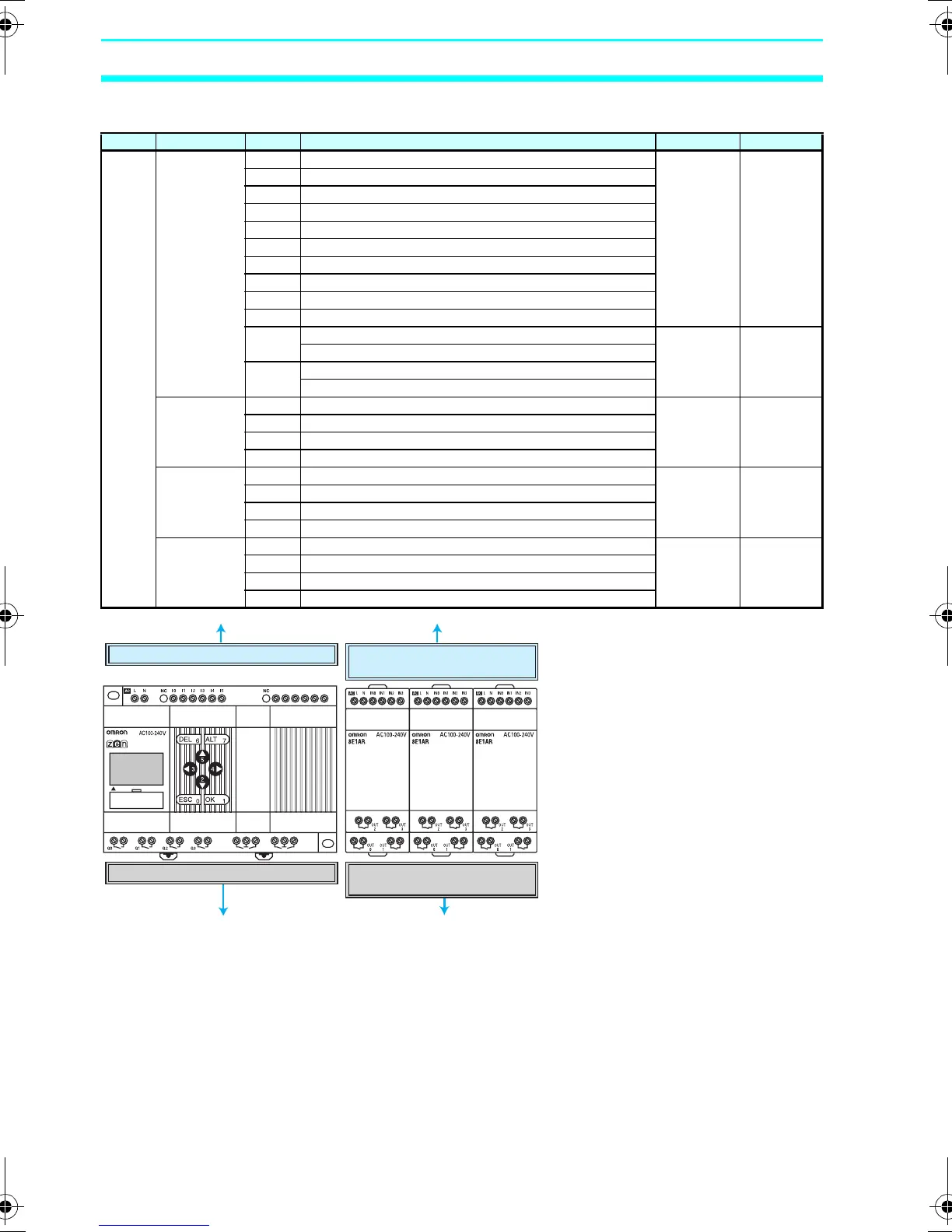
I/O Allocations for the ZEN-20C@@@-@-V2
I/O Unit name Bit Input device name Input IN filter
Input
bits
CPU Unit I0 AC DC V Yes No
I1
I2
I3
I4
I5
I6
I7
I8
I9
Ia Normal input AC DC V Yes No
Analog voltage input
Ib Normal input
Analog voltage input
Expansion
I/O Unit
X0 AC DC V Yes No
X1
X2
X3
Expansion
I/O Unit
X4 AC DC V Yes No
X5
X6
X7
Expansion
I/O Unit
X8 AC DC V Yes No
X9
Xa
Xb
Q
4
I
6
I
7
I
8
I
9
I
a
I
b
Q
6
Q
5
Q
7
20C1AR-A-V2
CPU Unit IN I0 to Ib
CPU Unit OUT Q0 to Q7
Expansion I/O Unit OUT Y0 to Yb
(Bits allocated in order of connection.)
Expansion I/O Unit OUT X0 to Xb
(Bits allocated in order of connection.)
Z211-E1-03.book Page 158 Friday, November 21, 2008 10:38 AM