56
70
71
TRIO Panel Formwork
Instructions for Assembly and Use – Standard Configuration
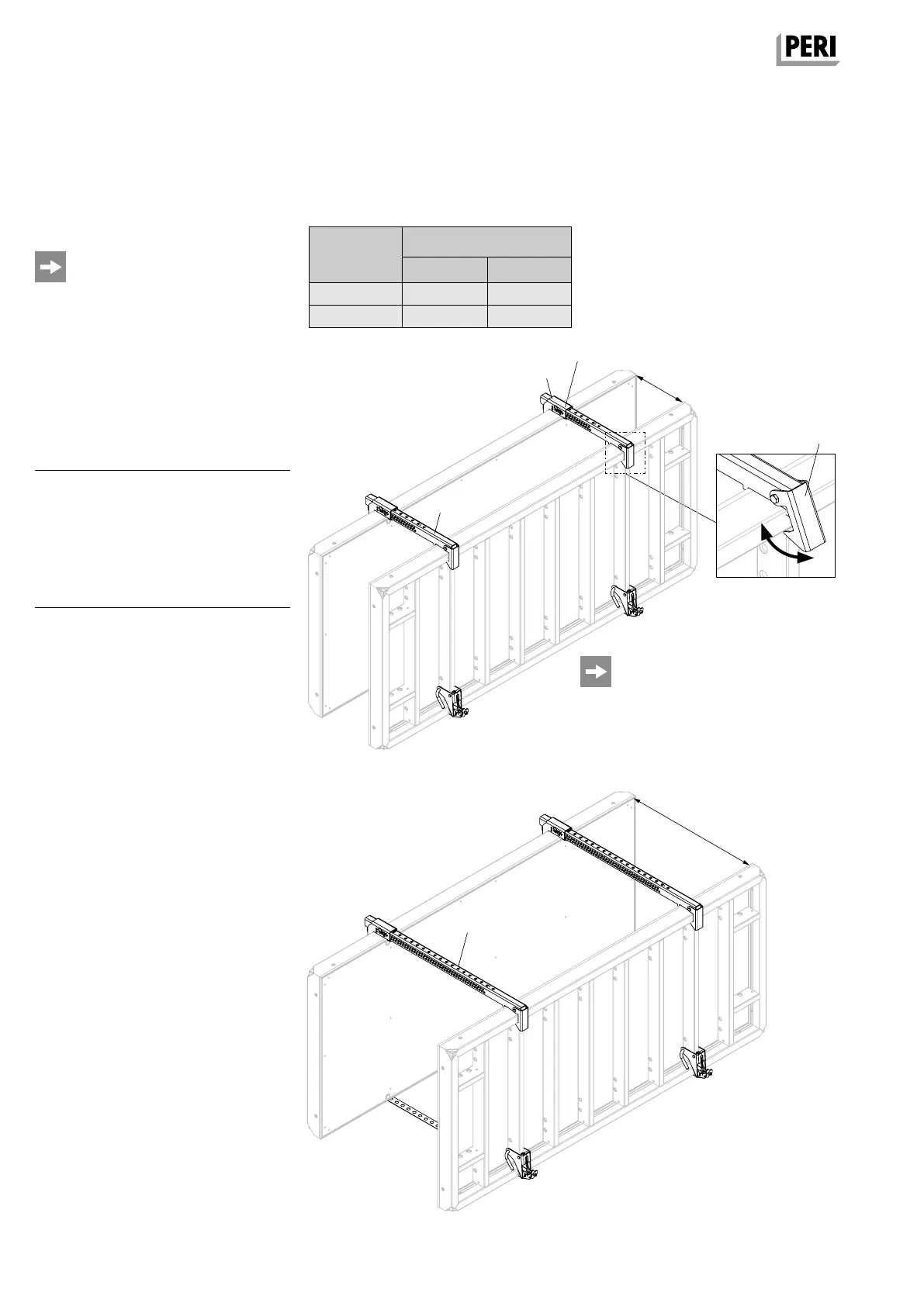
Fig. A15.01
Fig. A15.01a
Fig. A15.02
Depending on the wall thickness, the following table shows which
Tension and Compression Brace can be used.
≤ 100
≤ 40 cm
≤ 100 cm
Tension and Compression
Brace
MX15-40 and MX 15-100
Perm. tension and compression
force = 9 kN.
For max. height = 1.20 m, e.g. parapets.
Adjust Tension and Compression
Brace to:
Setting dimension =
wall thickness + 5 mm
Pos. Components Item no.
70 Tension and Compression
Brace MX 15-40 115350
70.1 Safety Hook
70.2 Mounting Shoe
70.3 Spacer Rack
71 Tension and Compression
Brace MX 15-100 123842
Preparation
1. Adjust Mounting Shoe (70.2) of the
Tension and Compression Brace to
required setting dimension:
– Remove cotter pin from bolt.
– Pull bolt out of Spacer Rack.
– Slide holes of the Mounting Shoe
(70.2) and Spacer Rack (70.3) on
top of each other according to the
setting dimension.
– Insert bolts through holes.
– Insert cotter pin into the hole of
the bolt.
2. Swing Safety Hook (70.1) of the
compression brace upwards.
(Fig. A15.01a)
J Tension and Compression Brace
is opened for positioning.
3. Oil the Spacer Rack (70.3).
Assembly
1. Place Tension and Compression
Brace on the panel; at the same time,
mount the Mounting Shoe (70.2) in
the edge profile of the formwork.
2. Press the Safety Hook (70.1) down-
wards over the edge profile and the
panel strut of the formwork.
J Tension and Compression Brace is
locked in position.
Wall
thickness
Tension and
Compression Brace
MX 15-40
MX 15-100
≤ 40
Clean the Spacer Rack (70.3) of the
Tension and Compression Brace after
concreting.
A15 Parapets, Foundations, Beams
Wall thickness
– Wall thickness ≤ 40 cm:
MX 15-40 (Fig. A15.01)
– Wall thickness ≤100 cm:
MX 15-100 (Fig. A15.02)
x x
– x
70.1
70.3
70.2
AuV TRIO EX.indb 56 11.10.17 09:49