41
58
TRIO Panel Formwork
Instructions for Assembly and Use – Standard Configuration
A13 Working and concreting platforms
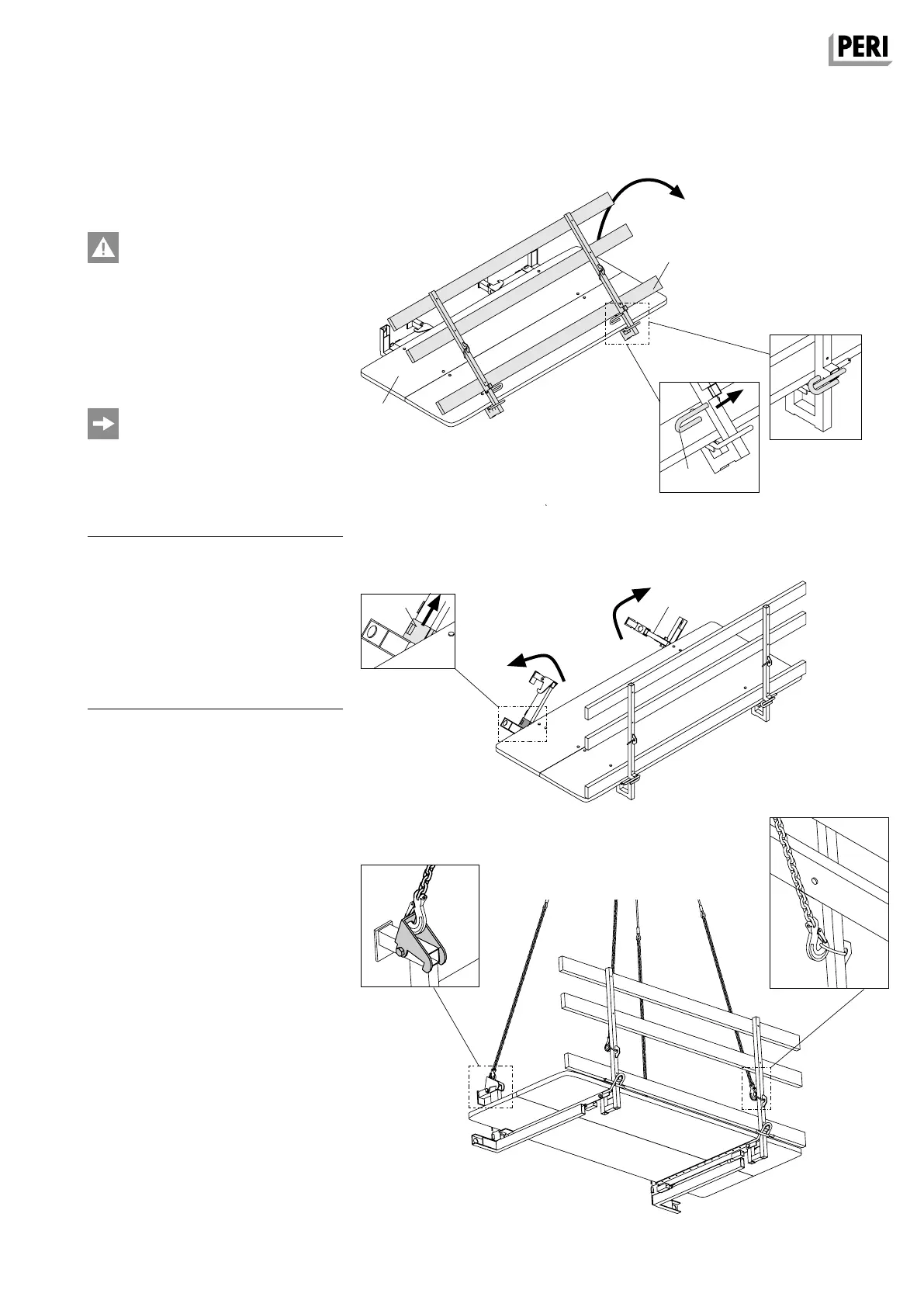
Fig. A13.01
Fig. A13.02
Fig. A13.03
Fig. A13.01a
Fig. A13.01b
Fig. A13.02a
Fig. A13.03a Fig. A13.03b
View from the inner
side of the boards
Concreting Platform
TRIO 120 x 270
The Concreting Platform TRIO
120 x 270 must be dismantled during
temporary storage of the panels.
Perm. load: 150 kg/m²
Load Class 2 according to
DIN EN 12811-1.
The load-bearing points of the
Concreting Platform TRIO 120 x 270
are coloured yellow.
Pos. Components Item no.
10 TRIO Panel according to size
10.7 Frame profile
58 Concreting Platform
TRIO 120 x 270 022950
58.1 Guardrail
58.2 Bolts
58.3 Suspension beam
58.4 Sliding sleeve
58.5 Retaining claw
Preparation
1. Fold up guardrail (58.1). (Fig. A13.01)
2. Secure guardrail with bolts (58.2).
(Fig. A13.01a + A13.01b)
3. Fold up suspension beam (58.3).
Ensure that the sliding sleeve (58.4)
is at the top.
(Fig. A13.02 + A13.02a)
4. Push sliding sleeve (58.4) down-
wards.
5. Attach 4-sling lifting gear to the
TRIO Concreting Platform.
(Fig. A13.03 + A13.03a + A13.03b)
58.1
58.4
58.3
58.2
AuV TRIO EX.indb 41 11.10.17 09:47