27
18
18
18
18
50
60
30
60
60
60
25
24
20
18
35
60
40
60
14
15
20
20
5
14 15
20
TRIO Panel Formwork
Instructions for Assembly and Use – Standard Configuration
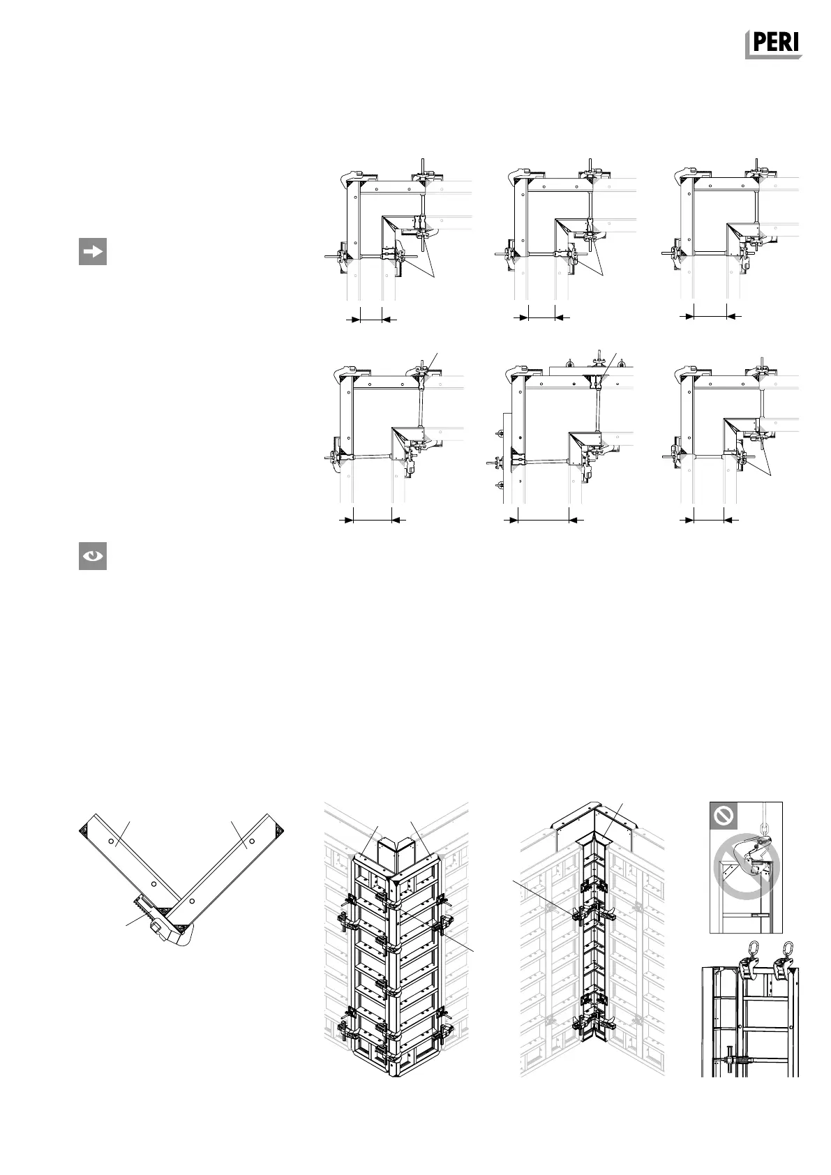
A7 Corners
Right-angled corners
Wall thicknesses from 18 cm to 40 cm
can be continuously formed.
(Fig. A7.01)
– Wall thickness 30 cm without
adjustment
– Internal adjustment for wall
thicknesses < 30 cm
– External adjustment for wall
thicknesses > 30 cm
Adjustment takes place with Wall
Thickness Compensator WDA (18)
or compensation (50) supplied by
contractor.
For the number of Alignment
Couplers for other panel heights,
see TRIO Poster.
Internal corner consisting of:
– TRIO Inside Corner TE (5) or Internal
Corner TAE (Alu)
– Alignment Coupler BFD (20)
(2 x BFD for h = 2.70 m) (Fig. A7.04)
– Always transport TRIO Inside Corners
in combination with the next panel.
Attach Lifting Hook to the next panel
(high profi le)! (Fig. A7.04a)
External corner consisting of:
– Panel TR 60 (14)
– Panel TR 72 (15)
– Alignment Coupler BFD (20)
(5 x BFD for h = 2.70 m)
(Fig. A7.03)
As seen from the outside, the Panel
TR 72 (15) must always be positioned
on the right and Panel TR 60 (14)
covers the front side.
Ensure that the Alignment Coupler BFD
is correctly installed. (Fig. A7.02)
Fig. A7.01
Fig. A7.03
Fig. A7.02
Fig. A7.04aFig. A7.04
per 2 WDA 5/6
TR 72
TR 60
TR 72
TR 72
1 WDA 5/6
TR 72
TR 72
2 WDA 5
X
TR 72
per 1 WDA 5/6
TR 72
AuV TRIO EX.indb 27 11.10.17 09:46