21
20
2
1
3
TRIO Panel Formwork
Instructions for Assembly and Use – Standard Configuration
A4 Panel connections
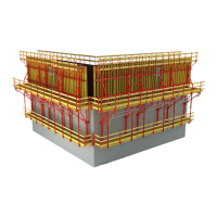
Assembly
1. Place wedge (20.1) in upper end
position. (Fig. A4.03)
2. Open sliding part (20.2).
3. Place Alignment Coupler BFD (20)
on the panel strut (10.3).
4. Close sliding part. Continuous
adjustment using the keyway (20.4)
is possible.
5. Secure wedge. (Fig. A4.04)
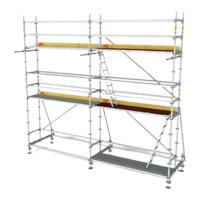
J The Alignment Coupler BFD (20) is
now mounted.
If the Wedge Head (20.5) is up against
the sliding part, there is no clamping
effect! (Fig. A4.02b)
In this case: release wedge, re-position
the sliding part and secure once again
with the hammer. (Fig. A4.02a)
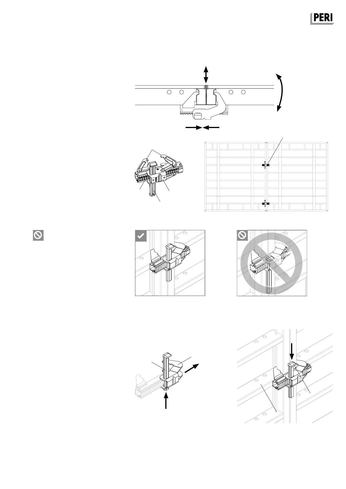
Alignment Coupler BFD
By hammering in the wedge, the panel
connections are:
1. Flush
2. Aligned
3. Tight (Fig. A4.01)
Areas of use:
– Standard panel joints
– External corners, internal corners,
see A7
– Oblique and acute-angled corners,
see A8
– Stopend formwork, see A12
– Filler timber, see A11
– Extensions, see A14
Quantity
2 x Alignment Coupler BFD (20) with
h = 2.70 m on the standard panel joint.
(Fig. A4.02)
Fig. A4.02
Fig. A4.03
Fig. A4.04
Fig. A4.01
Fig. A4.02bFig. A4.02a
20.3
20.4
20.2
20.1
20.1
20.2
20.5
10.3
AuV TRIO EX.indb 21 11.10.17 09:46