60
90
10
TRIO Panel Formwork
Instructions for Assembly and Use – Standard Configuration
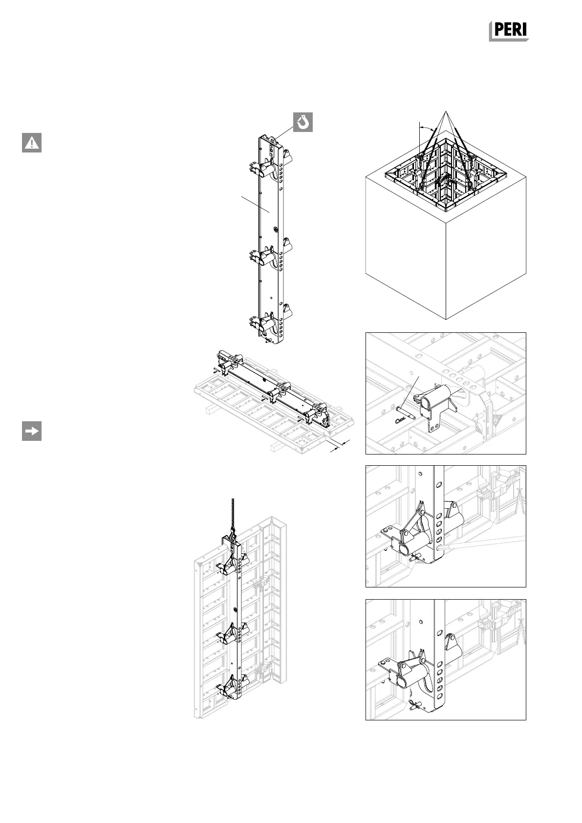
A17 Shaft formwork
Shaft Element TSE
Load-bearing capacity 2.0 t!
For fast striking and moving of TRIO
Shaft Formwork.
Assembly
1. Insert Shaft Element (90) between
two TRIO Panels. (Fig. A17.01)
2. Secure with bolt and cotter pin (90.1).
(Fig. A17.02)
– Panel TR 30 is secured using the
inner drilled holes.
– With TRIO Panel TR 60, 72, 90 and
120, secure in the outer bore hole.
3. Transport panel unit to place of use
and attach to the internal formwork
with the Alignment Couplers BFD.
(Fig. A17.03)
4. Bring shaft element into shuttering
position by means of a crowbar.
Press formwork lever downwards.
(Fig. A17.04a + A17.04b)
5. Anchor through the shaft element.
– Minimum internal shaft width 1.30 m.
– With Panel TR 30 upwards, there is
the possibility of connecting the
panels with the Shaft Element TSE.
– It is not possible to connect the Panel
TR 24 and TRIO Inside Corner TU.
Fig. A17.01
Fig. A17.03
Fig. A17.0 4b
Fig. A17.02
Fig. A17.0 4a
≤ 30°
2 t 2 t
2 t
2 t
90.1
AuV TRIO EX.indb 60 11.10.17 09:49