PG DRIVES TECHNOLOGY
95
CHAPTER 5 - DUAL
SK77898/2
.
15mm 0.6"
(HOLE CTS)
(HOLE CTS)
42mm 1.65"
11mm
0.43"
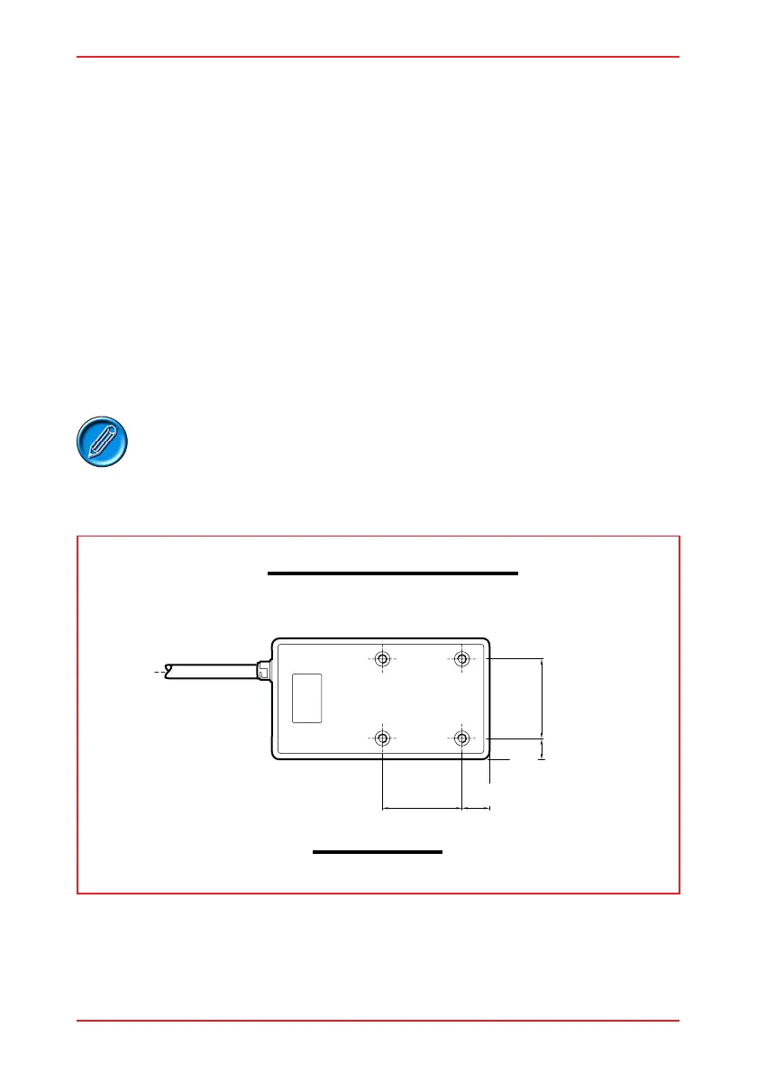
View of underside
MOUNTING HOLE POSITIONS
42mm 1.65"
3 Installation
The dual module has four holes for mounting on the underside. Refer to the following
illustration for details of the hole positions. The holes are tapped with an M5 thread to
a depth of 10mm (3/8").
The dual module is not sensitive to mounting orientation except where it is exposed to
water or dust. In this situation the control system must be mounted with the joystick
shaft pointing vertically upwards to maintain resistance to IPx4 as stated on the data
sheet:
Do not mount the dual module in a position which would expose it to excessive shock
or vibration. The dual module is designed to withstand levels of shock and vibration
experienced when mounted to the chassis of a wheelchair; and has been tested in
accordance with BS2011 part 2.1Eb (1987) and BS2011 part 2.1Fd (1973) for Bump
and Random Vibration respectively. Direct impacts onto the dual attendant system
should be avoided.
Contact PGDT if you need further advice.
When the dual module has been installed and connected the
joystick may need reorientatoion. Refer to section 5 of this
part of the manual for details.