VR2 CONTROL SYSTEM
SK77898/2
PG DRIVES TECHNOLOGY
66
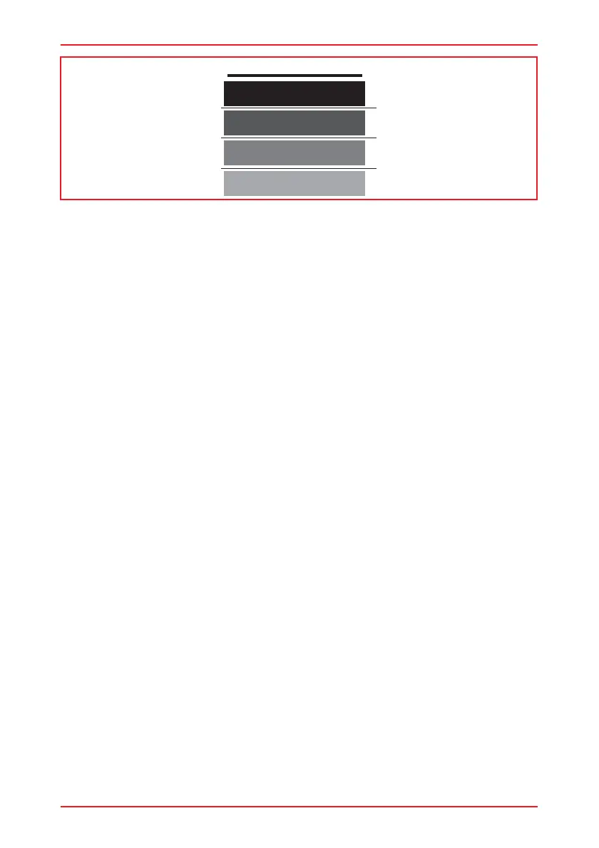
VR2 INHIBIT BANDS
Band 0
Band 1
Band 2
Band 3
12%
34%
- 2K2 = 22%
- 4K4 = 44%
54%
Upper Level Threshold 54%
Middle Level Threshold 34%
Lower Level Threshold 12%
This gives a band arrangement as below.
As good practice, the threshold limits have been chosen so the actual resistance
values that trigger a change are in the approximate center of the bands, thereby
eliminating the risk of a system erroneously switching between bands.
The 4 Speed Limits for Inhibit 2 would need to be set as below:
Inhibit 2:
Speed Limit in Band 0 100%
Speed Limit in Band 1 50%
Speed Limit in Band 2 25%
Speed Limit in Band 3 0%
6.15.2Actuator Inhibit Examples
Application 1:
In an identical fashion to the previous example, a wheelchair is fitted with a lifting
seat and as the seat raises the maximum speed is reduced to 50%, then 25% and
a full drive inhibit occurs at maximum height. Additionally, it is required to completely
inhibit the tilt function at maximum lift height. The VR2 is connected so that Actuator
Channel 1 drives the lift motor and Actuator Channel 2 drives the tilt motor.
An identical circuit to that of the previous example could be used.
Programming for the Inhibit 2 Threshold Levels and Inhibit 2 Speed Limit in Band x
parameters would also be identical to the previous identical
As it is the tilt motor, which is connected to Actuator Channel 2, the Actuator Channel
2 Up Inhibit and Actuator Channel 2 Down Inhibit parameters would need to be
programmed as follows.