PG DRIVES TECHNOLOGY
83
CHAPTER 4 - LIGHTING
SK77898/2
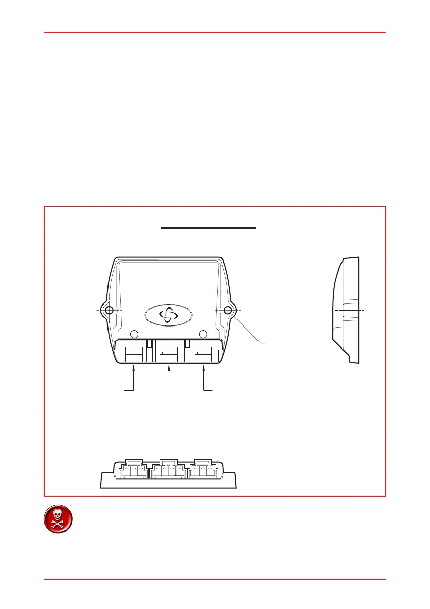
1 2
LEFT
SIDE
LIGHTS
+ INDICATORS
TO VR2
RIGHT
SIDE
LIGHTS
+ INDICATORS
FIXING
HOLES
MOUNT THIS WAY UP
3 Lighting Module Installation
3.1 Mounting
The lighting module should be mounted vertically, with the connector sockets pointing
down, using M3.5 (Europe) or #6-40 (USA) screws.
The lighting module must be mounted in a position where it is not exposed to conditions
of water or dust above those specified in ISO7176/9.
Do not mount the lighting module in a position which would expose it to excessive
shock or vibration. The lighting module is designed to withstand levels of shock and
vibration experienced when mounted to the chassis of a wheelchair; and has been
tested in accordance with BS2011 part 2.1Eb (1987) and BS2011 part 2.1Fd (1973)
for Bump and Random Vibration respectively. Direct impacts onto the lighting module
should be avoided. Contact PGDT if you need further advice.
It is possible for the case temperature of the Lighting Module
to rise above 41°C (107°F). For this reason the Lighting Module
should be fixed in a position where it cannot be touched by
the wheelchair user.