PG DRIVES TECHNOLOGY
79
CHAPTER 4 - LIGHTING
SK77898/2
1 Introduction
This section of the manual describes the operation, installation and programming
differences generated by the VR2 lighting system.
The VR2 lighting system comprises of:
VR2-L: VR2 fitted with lighting control buttons, and connection to a VR2
lighting module (VR2-LM)
2 Controls
There are common controls between the VR2 and VR2-L control system which operate
as previously described in Chapter 1. Where a control has been moved this will be
noted, however where a control has changed a description of its new functionality
and use will be given.
All information regarding handling advice, cleaning requirements and overall control
described in Chapter 1 should be followed.
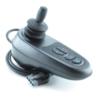
Refer to the following illustration for the new VR2-L control layout.
2.1 Actuator Button and LEDs
Depending on whether the VR2 is programmed with 1 or 2 actuators, the operation of
this button will differ. Refer to the relevant section below.
For actuator programming refer to Chapter 3 section 3.6
2.1.1 Wheelchairs with One Actuator
Depressing the actuator button once will enter actuator adjustment mode. This will be
indicated by the illumination of both actuator LEDs. Actuator adjustment can then be
made by deflecting the joystick forwards and backwards.
To re-enter drive mode depress the actuator button again or depress either speed
button
2.1.2 Wheelchairs with Two Actuators
Depressing the actuator button will enter actuator adjustment mode. Depressing the
button once illuminates the LEFT LED, and deflection of the joystick forwards or
backwards will adjust the actuator connected to that channel. Selection between the
two actuators is achieved by deflecting the joystick to the left and right. As the actuator
selected changes then so will the LED, which illuminates. LEFT for actuator 1 and RIGHT
for actuator 2.