PG DRIVES TECHNOLOGY
107
CHAPTER 6 - SERVICING & DIAGNOSTICS
SK77898/2
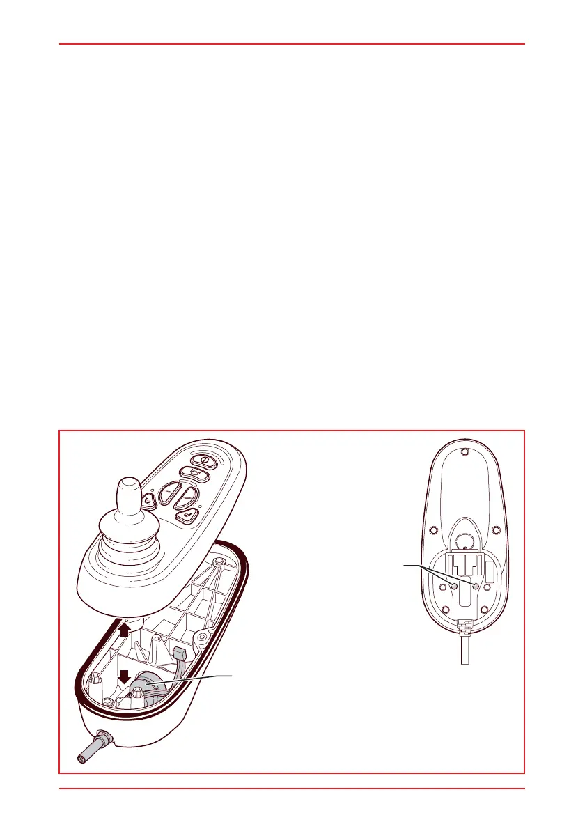
Charger Connection & Cable
Base Plan View
Retaining
Screws x2
Gasket
If the replacement or the calibration sequence has been unsuccessful the TruCharge
display will flash 7 bars. Refer to Diagnostics Chapter.
If the Joystick does not operate correctly, or if the calibration sequence does not
appear, then run through the following:
Check that Joystick Module is receiving power from the Power Module.
- The LEDs should light up
Repeat the replacement procedure, ensuring that all the cables are securely
connected and that the connectors clean, clear and not damaged.
Repeat the calibration procedure.
1.3 Joystick Cable Replacement
1.3.1 Joystick Cable Removal
Isolate the Joystick Module by disconnecting the Joystick Cable from the
Power Module.
Remove the 5 retaining screws from the underside of the Joystick Module.
Disconnect the Serial Cable from the PCB.
Remove the 2 retaining screws holding the Charger Socket and Cable.
Slide the Charger Socket and Cable out of the plastic base.