VR2 CONTROL SYSTEM
SK77898/2
PG DRIVES TECHNOLOGY
26
3 Mounting
3.1 Joystick Module
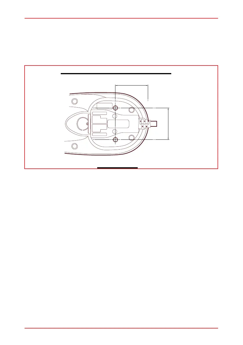
The VR2 Joystick Module has two holes for mounting on the underside. The holes are
tapped with an M5 thread allowing for a maximum screw penetration depth of
8mm (5/16)
3.1.1 Orientation
The control system is not sensitive to mounting orientation except where it is exposed
to water or dust. In this situation the control system must be mounted with the joystick
shaft pointing vertically upwards to maintain resistance to IPx4 as stated on the data
sheet:
If you want to use any other mounting attitudes then contact PGDT for advice.
3.1.2 Position
Do not mount the control system in a position which would expose it to excessive
shock or vibration. The VR2 control system is designed to withstand levels of shock
and vibration experienced when mounted to the chassis of a wheelchair; and has
been tested in accordance with BS2011 part 2.1Eb (1987) and BS2011 part 2.1Fd
(1973) for Bump and Random Vibration respectively. Direct impacts onto the control
system should be avoided.
3.2 Power Module Mounting
Fix the Power Module to the wheelchair chassis using suitable M5 or equivalent
hardware.
3.2.1 Orientation
The function of the Power Module is not sensitive to mounting orientation; however, it
should be mounted in such a way that water cannot enter and remain in the
connector recesses. It is recommended that the unit is not mounted with the
connectors uppermost. The Power Module has an IPX4 dust and water resistance
rating.
JOYSTICK MOUNTING HOLE POSITIONS
View of underside
42mm / 1.65" Nom.
40.0mm / 1.57"