PG DRIVES TECHNOLOGY
61
CHAPTER 3 - PROGRAMMING
SK77898/2
6 Inhibit Parameters
The VR2 contains two highly versatile inhibit inputs that can be configured to provide
drive inhibit, speed limiting and actuator inhibit functions. These inputs are referred
to as Inhibit 2 and Inhibit 3.
Inhibit 2 is via a dedicated 2-way connector on the Power Module.
Inhibit 3 is via pin 3 of the On-board Charger connector on the Power Module.
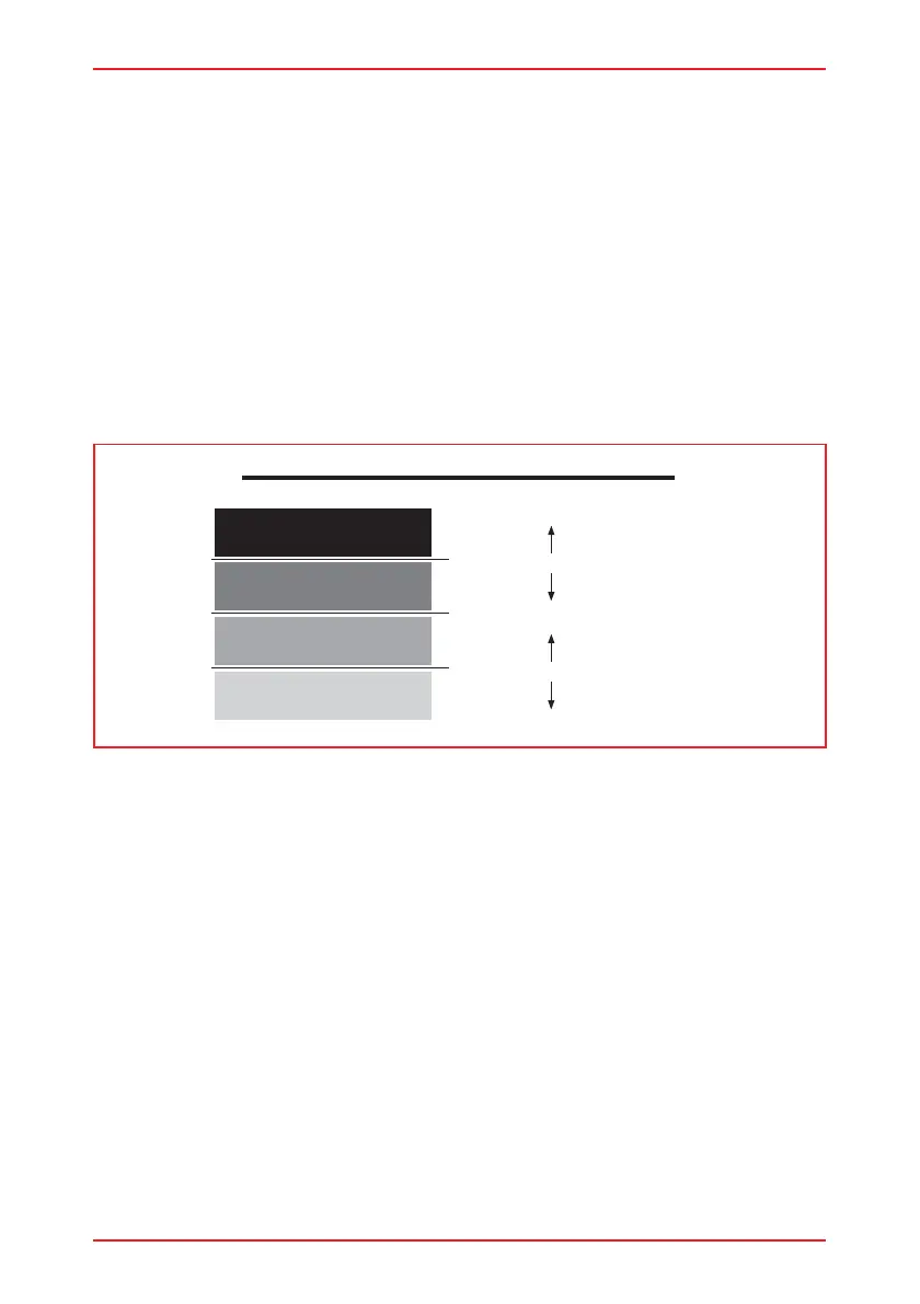
6.1 Inhibit 2 Threshold Level
Inhibit 2 has 4 possible input states, known as bands. Each band corresponds to a
range of electrical resistance connected to the input. The range or size of each
band is programmable, via three parameters, Inhibit 2 Lower Level Threshold, Inhibit
2 Middle Level Threshold and Inhibit 2 Upper Level Threshold.
The diagram below shows the concept.
100% corresponds to a resistance of 10KOhm or greater, including an open-circuit,
being connected to pin 1 of Inhibit 2.
0% corresponds to a short-circuit between pins 1 and 2 of Inhibit 2.
Each of the Level Threshold parameters can be set to a value of 0% to 100% in
steps of 1% meaning the range of each band is programmable. This allows for
versatile programming of drive inhibit, speed limit and actuator inhibit conditions
from just one input.
For details of drive inhibit and speed limit programming, refer to section 6.2.
For details of actuator inhibit programming refer to section 6.12
6.2 Inhibit 2 Speed Limit in Band x
This section must be read in conjunction with section 6.1.
There are 4 parameters that can be set:
Inhibit 2 Speed Limit in Band 0
Inhibit 2 Speed Limit in Band 1
Inhibit 2 Speed Limit in Band 2
Inhibit 2 Speed Limit in Band 3
VR2 THRESHOLD - BAND RELATIONSHIP
Band 0
Band 1
Band 2
Band 3
Upper Threshold Level
100%
0%
Middle Threshold Level
Lower Threshold Level