VR2 CONTROL SYSTEM
SK77898/2
PG DRIVES TECHNOLOGY
32
These recommendations are derived from well proven field experience of various
international wheelchair manufacturers. Nevertheless, manufacturers must confirm
these recommendations by carrying out suitable tests. Keep wire lengths as short as
possible.
Battery , motor and on-board charger wires should use Tri-
rated PVC equipment wire rated at 105°C.
5.3 Battery Wiring
The control system incorporates sophisticated current limiting circuitry as protection
for the circuits in the control system.
ISO 7176-14 requires you to provide protection against short circuits in the battery
wiring and the power loom or the extremely unlikely event of a short circuit in the
control system.
Place a suitable circuit breaker in series with the battery supply (refer to sections 3.1
+ 3.2), for example in the link between two 12V batteries. If your batteries are held in
separate enclosures, you must provide a circuit breaker with each of them.
The rating of the circuit breaker must match the capacity of the wiring used. We
recommend the use of a 70A circuit breaker. This recommendation is derived from
well proven field experience of various international wheelchair manufacturers.
Nevertheless, manufacturers must confirm these recommendations by carrying out
suitable tests.
ISO 7176-14 states that the minimum operating time for the circuit breaker when the
wheelchair is stalled is 15 seconds.
The chair manufacturer must install a suitable circuit breaker
to provide protection against short circuits in the battery
wiring, power loom or the control system. Failure to comply
with this could result in a fire hazard. PGDT accepts no
liability for losses of any kind arising from failure to comply
with this condition.
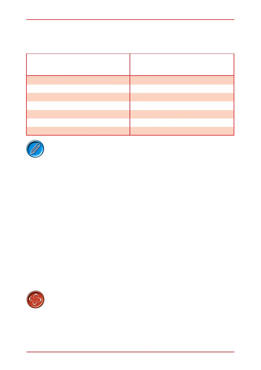
Connections Wire Gauge
Battery Wires
Motor Wires
On Board Charger Wires
Inhibit Wires
Actuator Wires
4.0mm
2
4.0mm
2
Battery Wires (VR2 40/50)
Motor Wires
VR2 40/50
2.5mm
2
2.5mm
2
1.0mm
2
0.5mm
2
1.0mm
2