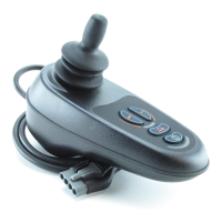
VR2 CONTROL SYSTEM
SK77898/2
PG DRIVES TECHNOLOGY
62
Each is programmable between 0% and 100% in steps of 1%.
The value in each bands parameter sets the wheelchairs maximum driving speed
when the VR2s Inhibit 2 input is in that band.
For example, if Inhibit 2 Speed Limit in Band 3 is set to 0%, then the drive will be fully
inhibited when the connection to Inhibit 2 is of a resistance within the range of Band
3.
For a more detailed example of actuator inhibits, refer to section 6.15.1
6.3 Inhibit 2 Operation
This parameter is only relevant if one of the Inhibit 2 Speed Limit in Band x values is
set to 0%, i.e. a drive inhibit. The parameter can be set to Latching or Non-latching.
If set to Latching, then the VR2 must be switched off and on again to resume drive
after an inhibit condition has occurred.
If set to Non-latching, then drive will be possible as soon as the inhibit condition is
removed.
If Inhibit 2 is set to latching, then the TruCharge battery gauge will flash 6 bars to
indicate a trip. See Chapter 1 section 8.3.
6.4 Inhibit 2 Debounce
This parameter sets the amount of time a connection to Inhibit 2 input must be
stable before it is interpreted as a valid condition. This parameter is particularly useful
for switch types that exhibit bounce, such as mercury switches, which are often
used on tilt mechanisms.
The parameter is programmable between 50ms and 500ms in steps 50ms.
6.5 Seat Reversal
The input Inhibit 2 can be configured to provide a seat reversal function. Seat reversal
is used on wheelchair models which can be converted from rear wheel drive to front
wheel drive by rotating the seat through 180°. The parameter for adjustment is Seat
Reversal, the effect of this parameter is explained below. For further details on
programming, refer to Chapter 3.
Seat Reversal can be set to On or Off.
ON Connecting the Inhibit 2 input to 0V will reverse the motors forward
direction. Motor direction and axes changes as normal and the Front
Wheel Drive Rate function is used.
OFF Seat Reversal has no effect.
6.6 Inhibit 3 Threshold Level
Inhibit 3 has 4 possible input states, known as bands. Each band corresponds to a
range of electrical resistance connected to the input. The range or size of each
band is programmable, via three parameters, Inhibit 3 Lower Level Threshold, Inhibit
3 Middle Level Threshold and Inhibit 3 Upper Level Threshold.
The diagram in section 6.1 shows the concept.

 Loading...