VR2 CONTROL SYSTEM
SK77898/2
PG DRIVES TECHNOLOGY
84
3.2 Connection
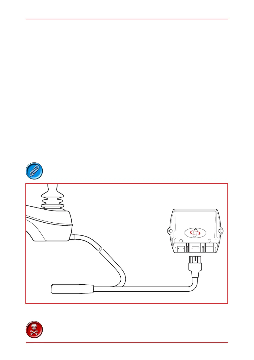
The lighting module has three connector sockets. Refer to the illustration in section 3.1.
3.2.1 Socket 1
This socket accepts a Hirose DF7 series 3 way connector for the control of the LEFT side
lights. Refer to the illustration in section 3.4 for details.
3.2.2 Socket 2
This socket accepts a Hirose DF7 series 3 way connector for the control of the RIGHT
side lights. Refer to the illustration in section 3.4 for details.
3.2.3 Socket 3
This socket is the power and communications connection form the VR2-L and accepts
the lighting module connection from the VR2-L spur. This socket has no identification
number
3.3 Output
The maximum current ratings of the Indicator and Lighting outputs are as stated below.
INDICATORS 3.5A
LIGHTS 1.75A
These outputs are self-protecting and do not require fuses
or circuit brealers.
LIGHTING
MODULE
1 2
To Power
Module
VR2-L
3.4 Wiring
For lighting module sockets 1 and 2 only use the exact parts
specified below for the mating connector.