VR2 CONTROL SYSTEM
SK77898/2
PG DRIVES TECHNOLOGY
68
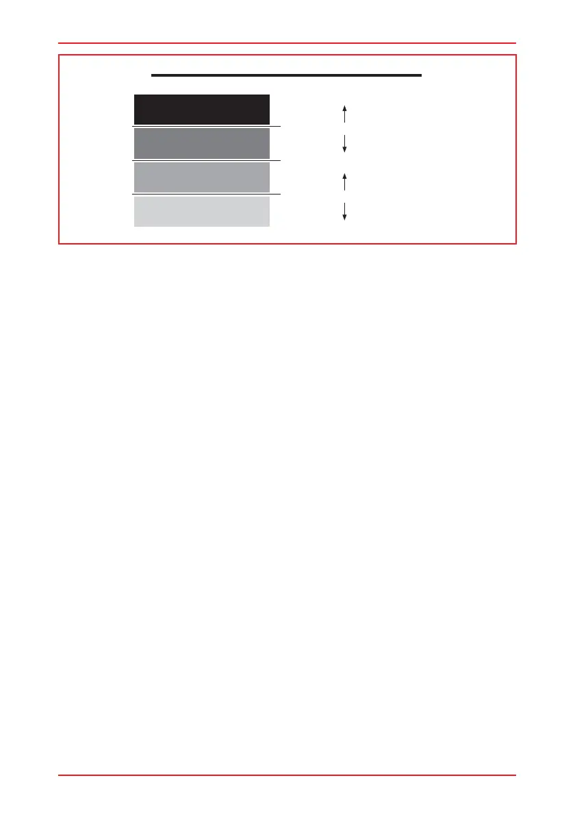
VR2 THRESHOLD - BAND RELATIONSHIP
Band 0
Band 1
Band 2
Band 3
Upper Threshold Level
100%
0%
Middle Threshold Level
Lower Threshold Level
This programming means that the Up movement will be inhibited when the Inhibit 2
input in Band 0, i.e. one end of recline travel, and that the Down movement will be
inhibited when the Inhibit 2 input is in Band 3, i.e. the other end of the recline travel.
Referring the Band diagram below, it can be seen that by programming Inhibit 2
Upper Level Threshold and Inhibit 2 Lower Level Threshold, then the actual angular
range of the recline mechanism is adjusted.
Note: Bands 1 and 2 are never used in actuator inhibits, so to give maximum
adjustment range in this example, then Inhibit 2 Middle Level Threshold is set to 50%.