45-5
02
~>
12
Servicing Vee Belts
EN
n DANGER
Under no circumstances should any
check on the belt tension be made whilst
the machine is running. There is an
entanglement hazard and risk of trapping
parts of the body.
Manual Adjustment
6. Observe all safety warnings.
15. Use the marks or measurements made before
adjustment to ensure that the correct pulley
alignment has been restored.
16. Tighten all locknuts and/or clamping bolts.
17. Ensure that all the drive guarding is replaced
and secured before start the plant.
14. To establish correct belt tension, use the
method described in ‘drive belt tensioning’.
7. Close down the plant and implement the
Lockout Procedure.
8. Remove guarding as necessary to gain access
to the Vee belt drive and tensioning elements.
9. Mark or measure the existing position, assuming
correct alignment, of the moving frame at each
tension screw.
10. Loosen the clamping bolts securing the moving
base frame [horizontal drives].
11. Undo locknuts on the tension screws to allow
the base frame to be moved in the required
direction.
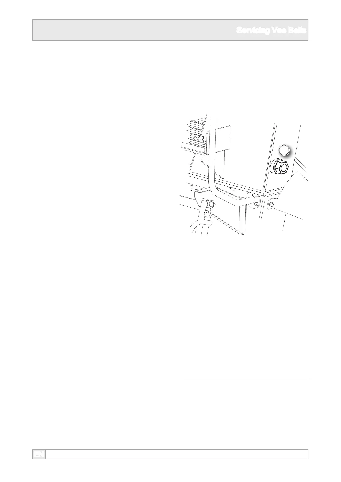
12. On the Pegson XH250, XH320 and XH320SR
the two adjusters are positioned as shown and
do not have locknuts.
13. Either by turning a nut on the screw or the
screw itself, depending on the type, tension or
slacken the drive belts as required. Make an
equal amount of adjustment to each screw.