45-6
02
5
6
10
7
11
7
11 12
8
9
13
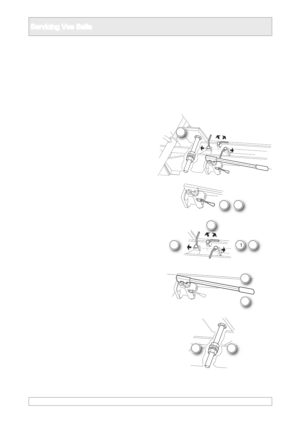
Servicing Vee Belts
1. Observe all safety warnings.
2. Close down the plant and implement the lockout
procedure.
3. Remove guarding as necessary to gain access
to the Vee belt drive and tensioning elements.
4. Mark or measure the existing position of the
moving frame at each tension screw, assuming
the frame is correctly aligned.
5. The hand operated hydraulic pump and controls
are positioned under the engine and frame.
6. Set hydraulic direction control to up.
7. Open each of the three valves in turn and
operate the pump to raise each cylinder and
take the weight of the engine and frame o the
nuts.
8. The centre valve operates two cylinders at the
belt end.
9. Release the appropriate locking nuts on the
support studs to enable the frame to be raised
to tighten the belts or lower to slacken.
10. Set the hydraulic direction control as required
to raise or lower.
11. Open each of the three valve in turn and
operate the pump to move the frame a little at a
time and keep it level.
12. Close all valves when in the nal level position
to maintain the position.
13. When the belts are tensioned correctly, tighten
all the locking nuts.
Vertical Belt Adjustment - Hydraulic Assisted, [only tted to some plants]