45-8
Servicing Vee Belts
1. Observe all safety warnings.
2. Close down the machine and implement the
Lockout Procedure.
3. Remove the guards from around the belt.
4. Calculate the deection distance in mm (or
inches) on a basis of 16mm (0.6in) deection
per 1 metre (1 yard) of belt span.
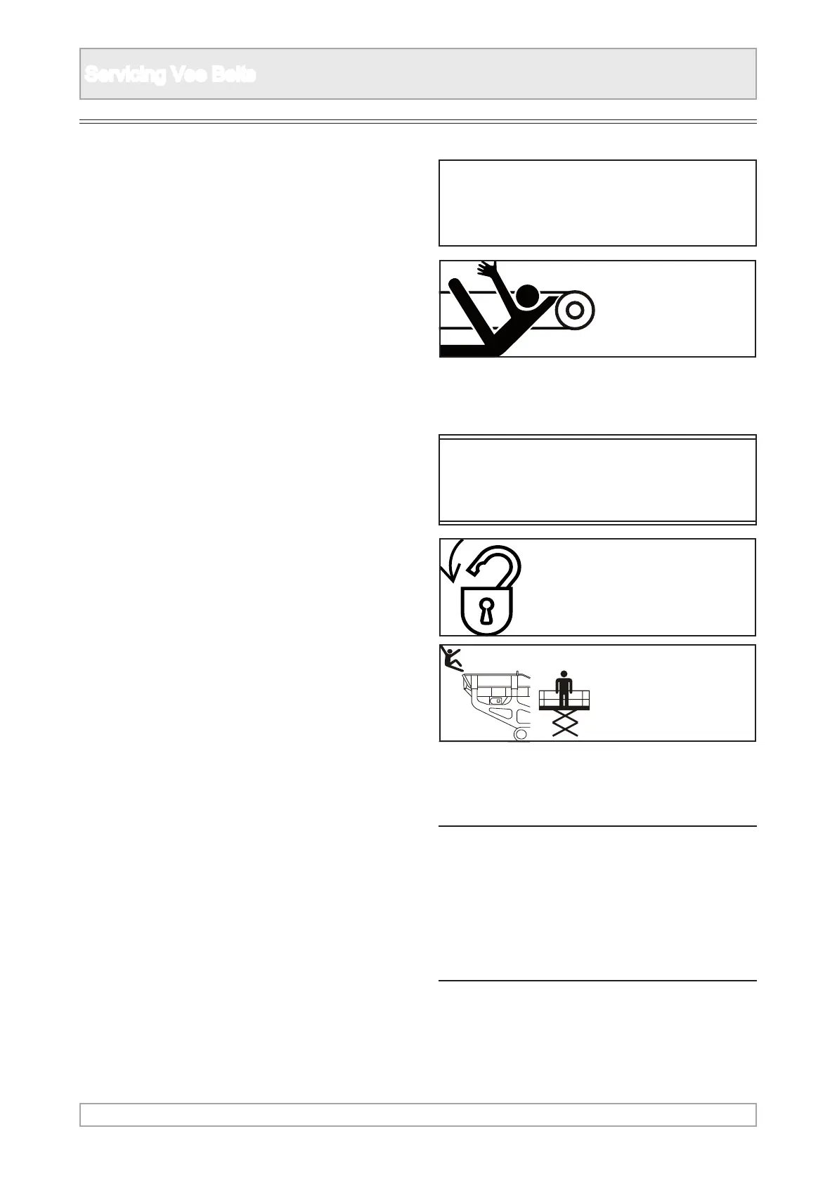
n DANGER
Under no circumstances should any
check on the belt tension be made whilst
the machine is running. There is an
entanglement hazard and risk of trapping
parts of the body.
ENTANGLEMENT
HAZARD
n DANGER
Refer to Safety Notices Section for relevant
warning and procedure
n WARNING
Refer to Safety Notices Section for relevant
warning and procedure
LOCKOUT
PLANT
FALLING
HAZARD
Drive Belt Tension
5. If a belt tension indicator is available:
METRIC: Centre to Centre Distance in metres
x 16 = Deection in mm.
a. Set the lower marker ring at the deection
distance required on the lower scale.
b. Set the upper marker ring against the bottom
edge of the top tube.
c. Place the belt tension indicator on top of the
belt at the centre of the belt span, and apply
a force at right angles to the belt deecting
it to the point where the lower marker ring is
level with the top of the adjacent belt.
d. Read o the setting force value indicated by
the top edge of the upper marker ring.
e. Compare this value to the value shown in the
table.