EIP Protocol PLX32-EIP-MBTCP-UA ♦ Multi-Protocol Gateway
User Manual
Page 66 of 156 ProSoft Technology, Inc.
March 8, 2018
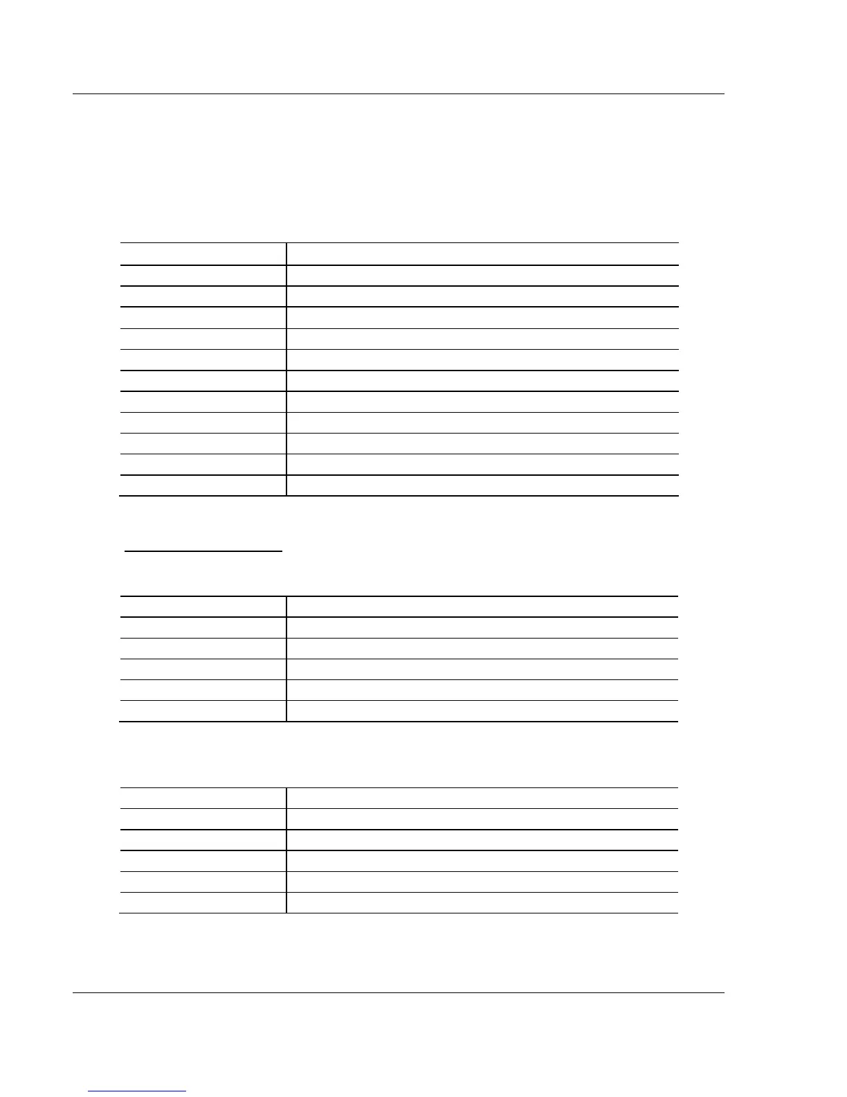
The first word in each client’s command list error data area contains the
status/error code for the first command in the client’s command list. Each
successive word in the command error list is associated with the next command
in the list. Therefore, the size of the command list error data area depends on the
number of commands defined.
The structure of the command list error data area (which is the same for all
clients) is displayed in the following table:
EIP Server Status Data
The following table lists the addresses in upper memory where the PLX32-EIP-
MBTCP-UA stores status data for each EIP server:
The content of each server’s status data area is structured the same. The
following table describes the content of each register in the status data area: