ULTRA 4 INSTRUCTION MANUAL
24
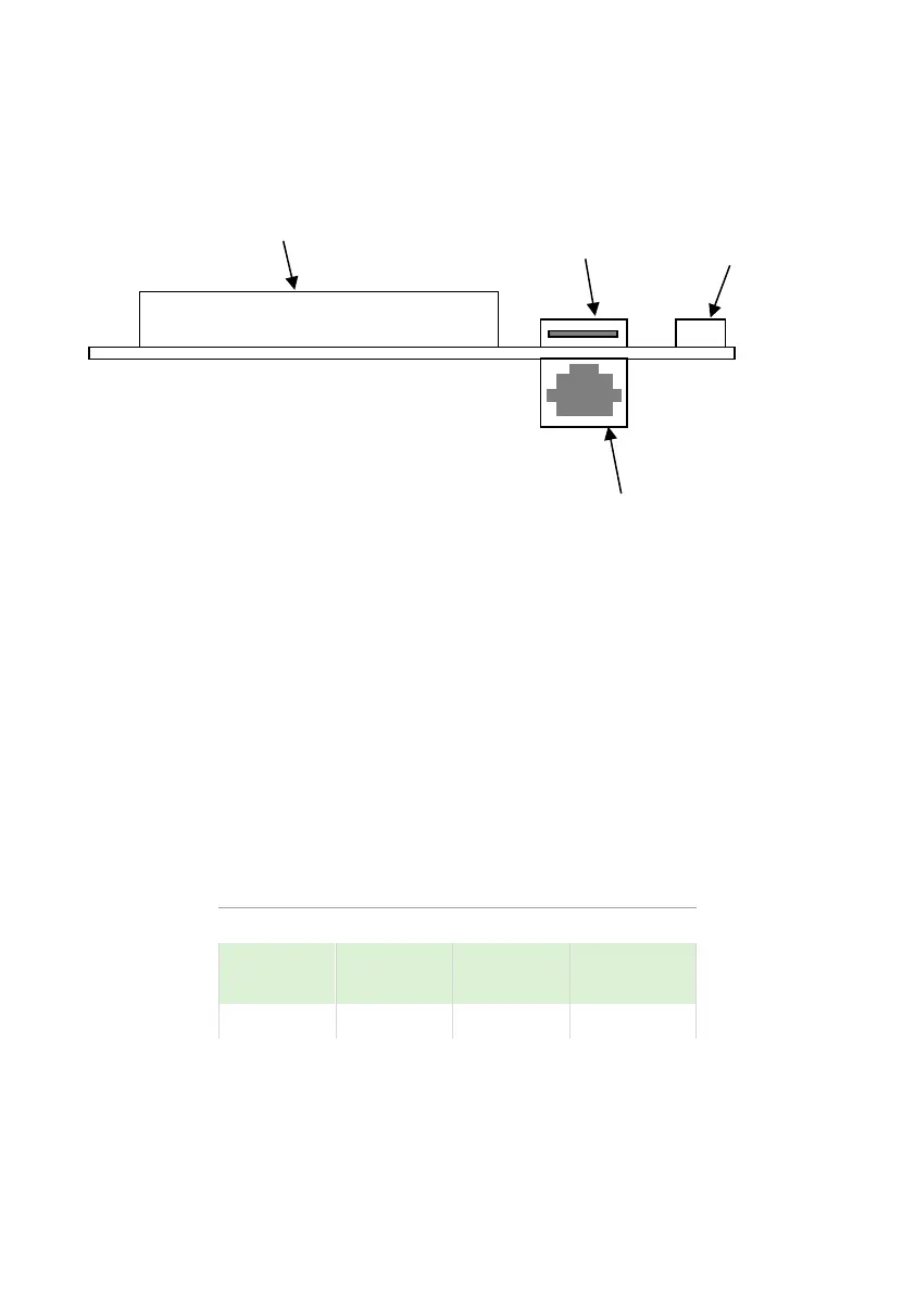
Interface Connections
The SD card slot labelled ‘SD’, and the RJ11 socket labelled ‘PC’ are situated
on the LCD display board as detailed below:
Terminal Connections
Power
Ultra 4 can operate from mains AC and automatically from DC or battery
backup in the event of a power failure or can be operated permanently from
DC or batteries.
Transducer/sensor
The transducer should be installed, and connected, in accordance with the
installation instructions contained in the Transducer User Guide.
The entire range of, standard dB transducers and mmWave dBR sensors are
certified for use in hazardous areas. See the product label for certification
details. Wire the transducer to the Ultra 4’s transducer terminals, as follows:
When using 2-core screened extension cable, the Black and Green wires of
the transducer should be connected to the screen of the extension cable
which in turn should be connected to the appropriate 0 volts’ terminal of the
Ultra 4.

 Loading...


