Руководство пользователя
3. Installing System Components 47
www.qtech.ru
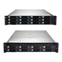
The 8 memory slots controlled by the motherboard CPU 1 are: DIMMA1, A2, DIMMB1,
B2, DIMM C1, C2 and DIMM D1, D2; The 8 memory slots controlled by CPU 2 are:
DIMME1, E2, DIMMF1, F2, DIMMG1, G2 and DIMMH1, H2,
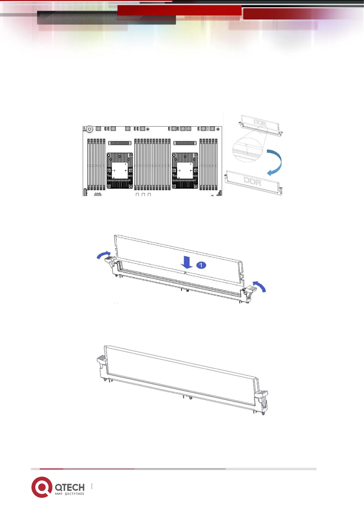
Note that the notch of the memory is consistent with the notch of the DIMM slot, and
each DIMM module is vertically snapped in place to prevent incorrect installation.
Figure 3-5
Figure 3- 6
Figure 3-7
 Loading...