Installation and Service manual
Compass STD 22
90
Edition: July 1, 20053646/110 --233.DOC010302
1 2 3
4 56
78
9
10
1112
13
14
15
123456 78 9
101112
13
14
15
E10
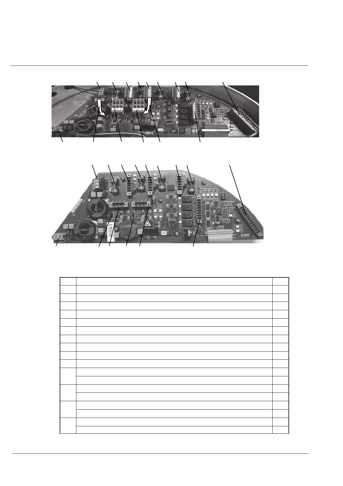
Figure 50: Arrangement of plugs, terminal boards and fuses on the
Connection PCB.
1
Terminal L1 Power supply (24VDC)
2 Fuse E1 (T10A) Power supply (24VDC)
3 Plug B2 Output Channel1 Course Bus/NMEA
4 Fuse E2 (T1A) Channel1 +24V
5 Plug B3 Output Channel2 Course Bus/NMEA
6 Fuse E3 (T1A) Channel2 +24V
7 Plug B4 Output Course Bus
8 Fuse E4 (T1A) Course Bus +24V
9 Plug B5 Input (+24V/Set QS/ Pulse Log/Pulse Log Dir./NMEA Log/GPS--receiver)
10 Plug B6 Output (QS/SEC/System/Available)
11 Plug B7 CAN1 bus
Plus B8 CAN2 bus
12
Switch B32 for CAN1 bus terminating resistor E10
Terminal Board L2 24V connection to Power S upply PCB
13
Plus B8 CAN2 bus E10
Jumper B31 for the CAN2 bus terminating resistor
14
Switch B31 for the CAN2 bus terminating resistor E10
Jumper B32 for the CAN1 bus terminating resistor
15
Terminal Board L2 24V connection to Power S upply PCB E10
 Loading...