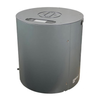
Compass
STD 22
Installation and Service manual
Compass STD 22
97
Edition: Feb. 17, 2006 3646/110 --233.DOC010302
3.4.3 Switching on, settling and adjustment
The STD 22 Compass switches on when the power supply is activated on the main
control panel for the Distribution Unit (once the Distribution Unit has been connected to
the STD 22 Compass).
3.4.3.1 Checks on the compass
Measuring the compass power supply voltage (on the compass).
This voltage must fall within the tolerance range (18 VDC to 36 VDC).
Terminal board L1
Power supply connection
Figure 57: Measuring the compass power supply voltage
Terminal board L1 terminal 1 +24VDC
Terminal board L1 terminal 2 0V
Note:
The absolute lower limit for the power supply v oltage is 18VDC, the absolute
upper limit is 36VDC!
When connecting cables, ensure that these values are adhered to.

 Loading...