Installation and Service manual
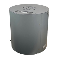
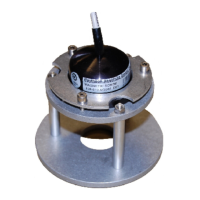
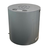
Compass STD 22
Compass STD 22 Compact
118
Edition: Feb. 17, 2006
3646/110 --233.DOC010302
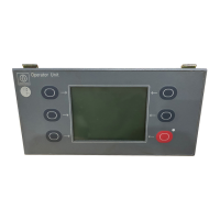
5.1 Overview of functions of all DIP switch settings
Serial
no.
DIP switch setting Function
1 Normal operation
2 Setting compass zero (Alignment error)
3 Set the repetition rate (1s/100ms) of the
NMEA heading data output and the output
with or without ROT
4 Set the CAN bus address
(for gyro compass STD 22 only)
5 Set the interfaces for Channel 1 and
Channel 2 (compass outputs)
6 Set the ROT turning direction
(Port+;STB--)
7 Bypass the settling phase (Service only)
8 Set the speed source for SEC
9 Check connected course receivers (course
data) (follow up turning)
Function check of RoT
10 Check the fan, the display and the follow-up.
DO NOT PERFORM DURING THE
HEATING PHASE!!
11 Turn off the follow-up system
(Service only)
12 Adjustments to read--out of data.
see following steps.
12
Step 1
Indicate encoder heading
 Loading...