EasyManuals Logo

Raytheon Anschütz STD 22 Compact GYRO COMPASS Installation And Service Manual

Raytheon Anschütz STD 22 Compact GYRO COMPASS
237 pages
To Next Page IconTo Next Page
To Previous Page IconTo Previous Page
Page #125 background imageLoading...
Page #125 background image
Compass
STD 22
Installation and Service manual
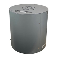
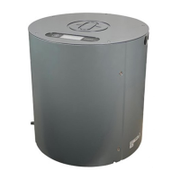
Compass STD 22
Compass STD 22 Compact
115
Edition: July 1, 2005 3646/110 --233.DOC010302
4 Fuses, jumper, LED‘s, buttons and plugs
The meaning and the location of fuses, jumper LED‘s, buttons and plugs of the 3 PCB‘s:
is given in the annex.
PCB
Part no. Part no. (E10)
Connection PCB NB05--365 110--233.X13
Power Supply PCB 110--233.102 110--233.X12
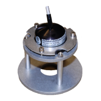
Sensor PCB 110--233.X08 110--233.X11
Outer Sphere PCB 110--233.101 110--233.X10
After removal of the cover this information can be helpful to locate a fault.

Table of Contents

Other manuals for Raytheon Anschütz STD 22 Compact GYRO COMPASS

Questions and Answers:

Question and Answer IconNeed help?

Do you have a question about the Raytheon Anschütz STD 22 Compact GYRO COMPASS and is the answer not in the manual?

Raytheon Anschütz STD 22 Compact GYRO COMPASS Specifications

General IconGeneral
BrandRaytheon Anschütz
ModelSTD 22 Compact GYRO COMPASS
CategoryCompass
LanguageEnglish

Related product manuals