Installation and Service manual
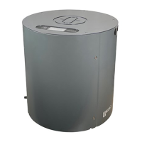
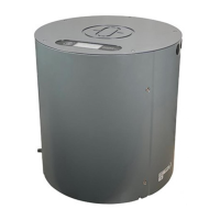
Compass STD 22 Compact
42
Edition: May 20, 2005
3646/110 --233.DOC010302
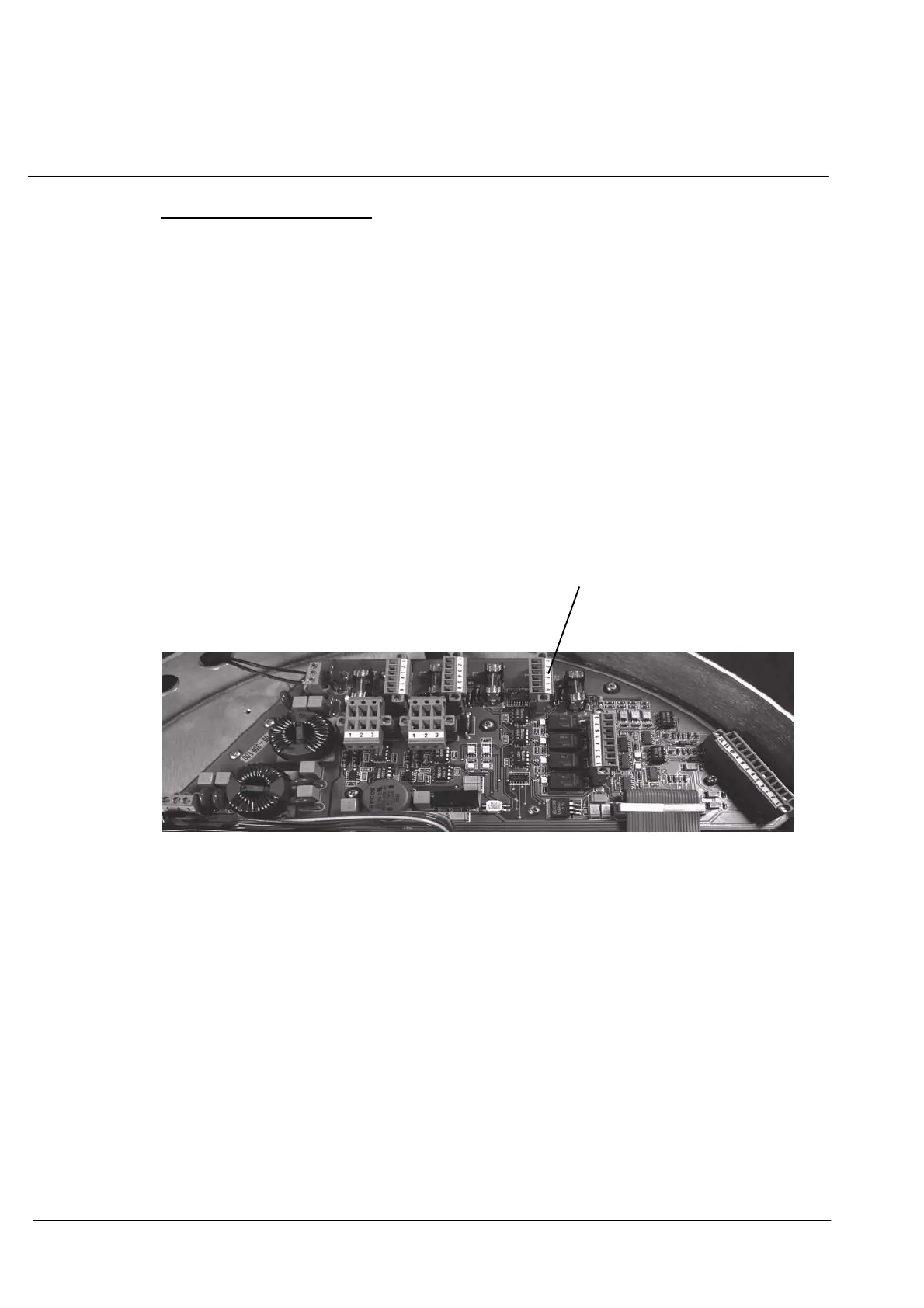
Making a signal connection:
(see also Cable and Connection Diagram 110--233.HP010
and wiring diagram 146--103.HP007)
A 2--core, screened cable with c onductor cross--section ≧1mm
2
is used to create a
connection between:
Plug B4 on Connection PCB of the STD 22 Compact Gyro Compass
Terminal 3 (TX+) und 4 (TX--)
and
terminal board L4, terminals 1 (Rx--) und 2 (RX+) of the Step/SSC Modules in the
Additional Output Box (siehe Figure 21).
Plug B4
Output 3
Figure 22: Connection of Course Bus in the STD 22 Compact Gyro Compass
The signal outputs from the Additional Output Box are created as shown in the drawings
-- Cable and Connection Diagram 110--233.HP010
and
-- Wiring diagram 146--103.HP007.
 Loading...