Compass
STD 22
Installation and Service manual
Compass STD 22
95
Edition: July 1, 2005 3646/110 --233.DOC010302
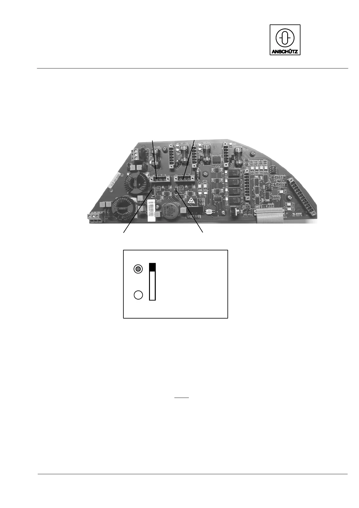
3.4.2.4 Switching the termination resistors for the CAN bus
(E10 only)
Plug B8
CAN2 bus
Plug B7
CAN1 bus
Switch B32
(for CAN2 bus)
Switch B31
(for CAN1 bus)
Closed (terminator set)
Open
(shown: “Open position”)
Switches B31 and B32
Figure 55: Switches B32 and B31 for CAN1 and CAN2 termination resistors
If a compass is to be used as a terminal device in a CAN bus application, both switches
(B32 and B31) must be set to the closed position. This position activates the terminating
resistors at the end of each CAN bus.
Each end of the CAN busses must
be terminated with a terminating resistor.
Failure not to set termination resistors (open bus) will cause sporadic error messages
from the bus concerned (see also manual 3648, Operator Unit 130--613).
 Loading...