Compass
STD 22
Installation and Service manual
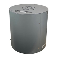
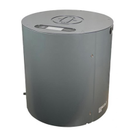
Compass STD 22
75
Edition: May 20, 2005 3646/110 --233.DOC010302
3.2 Creating cable connections
3.2.1 General information concerning on-board wiring
The cables which are to be connected to the STD 22 Gyro Compass are led through one
of the cable entries at the top of the c ompass enclosure and fixed in the cable entry with
a cable clip suitable for the size of the cable.
The cable entries are supplied with the compass.
Caution:
Ensure that cables are not live before creating cable
connections.
It is vitally important to ensure that all cables are free of
voltage; where appropriate, carry out voltage
measurements beforehand and/or disconnect the relevant
distributor from the power supply.
To ensure that the compass functions correctly, it is essential to adhere to the following
sequence when creating cable connections.
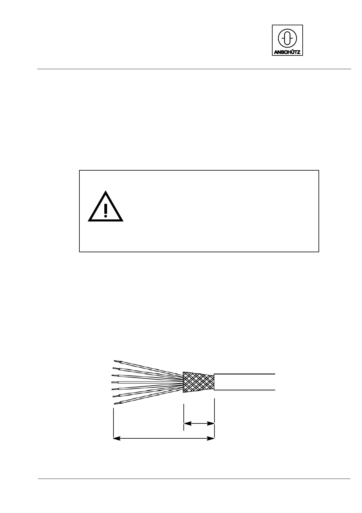
-- Strip the cable over a length of approximately 180 mm
(depending on the distance of the cable entry from the terminal).
Be careful not to damage the screening.
-- Trim the screening so as to leave approximately 15 mm on the cable.
approx.
15mm
approx. 180mm
Figure 37: Requirements for stripping the connecting cable
 Loading...