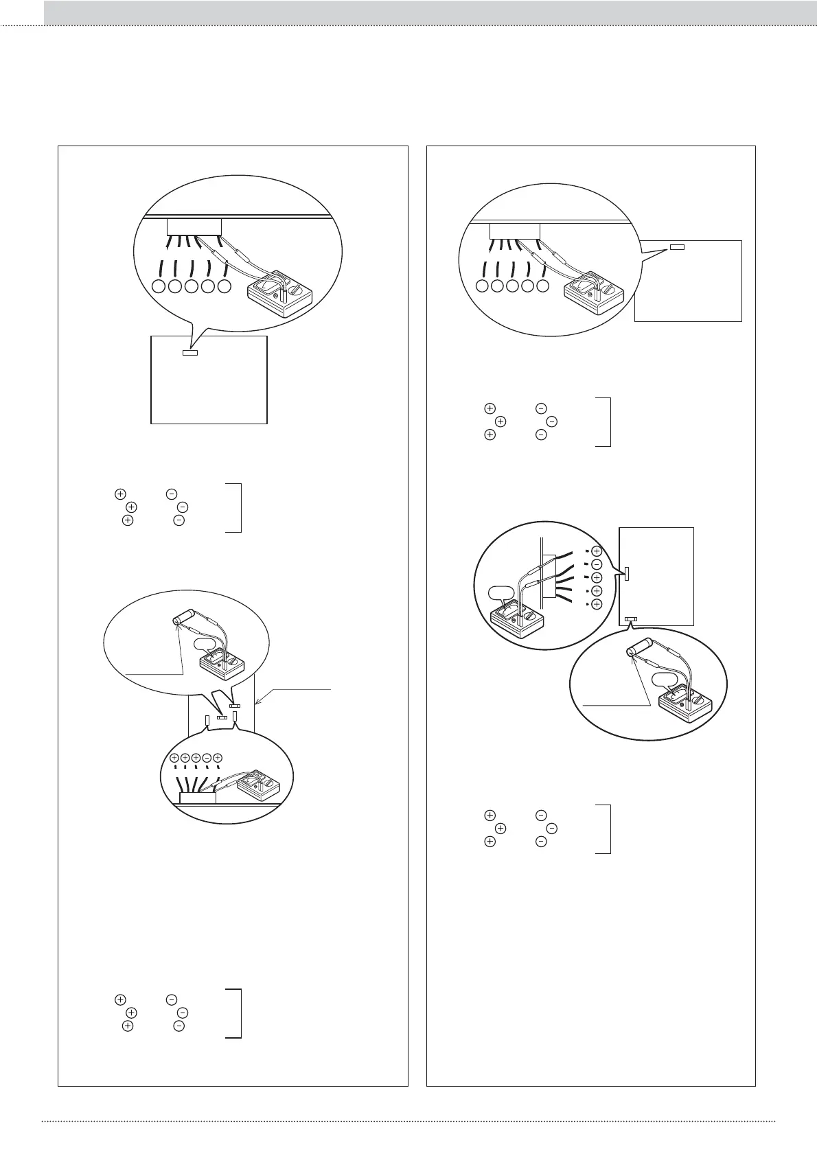
Measuring the voltage between the connector pins R.
Take the measurement R while heating or cooling.
Measure the voltage as described below without removing the connec-
tor R.
Voltage of the FAN MOTOR on the PCB MAIN
BL Y W B R
FAN MOTOR
+ + + +
-
PCB MAIN
18
18
Models 110 Fig. 2
Between red and black
ca. DC200-370V
Between yellow
and black
ca. DC3-7V
Between white
and black
ca. DC15V
PCB MAIN
It is operating normally
¼ FAN MOTOR error
BL Y W B R
Lower
Fuse: CF6
Upper
Fuse: CF7
(250V T3.15A)
0Ω
PCB MAIN
14
11
FAN MOTOR
Model - 116
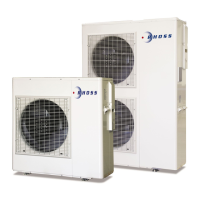
UPPER FAN MOTOR
Measuring the voltage between the connector pins K.
Take the measurement Kwhile heating or cooling.
Measure the voltage as described below without removing the connec-
tor K.
LOWER FAN MOTOR
Measuring the voltage between the connector pins N.
Take the measurement Nwhile heating or cooling.
Measure the voltage as described below without removing the connec-
tor N.
Between red and black
ca. DC200-370V
Between yellow
and black
ca. DC3-7V
Between white
and black
ca. DC15V
PCB MAIN
It is operating normally
¼ FAN MOTOR error
Voltage of the FAN MOTOR on the PCB
MAIN
BL BR R B W
+ + + +
-
PUMP
PCB MAIN
17
17
Models 105 - 110 Fig. 3
Measuring the voltage between the connector pins Q.
Take the measurement Q while heating or cooling.
Measure the voltage as described below without removing the connector Q.
Between red
and black
ca. DC200-370V
Between brown
and black
ca. DC3-7V
Between red
and black
ca. DC15V
PCB MAIN
It is operating normally
¼ Pump error
W
B
R
BR
BL
0Ω
0Ω
PCB MAIN
PUMP
Lower
Fuse: CF2
(250V T3,15A)
13
Model - 116
Measuring the voltage between the connector pins M.
Take the measurement M while heating or cooling.
Measure the voltage as described below without removing the connector M.
Between red
and black
ca. DC200-370V
Between brown
and black
ca. DC3-7V
Between red
and black
ca. DC15V
PCB MAIN
It is operating normally
¼ Pump error
108
Section II :: Installation and maintenanceEN