• 4. PLANT MANAGEMENT SYSTEM INTEGRATED "ELECTA"
KCTR
7 ÷ 45 °C
Fan coils
-20 ÷ +43 °C
18 ÷ 35 °C
Radiant panels 1
Thermostat
Valve by-pass
18 ÷ 35 °C
18 ÷ 35 °C
Radiant panels 2 Radiant panels 3
Thermostat
Storage tank 50 ℓ
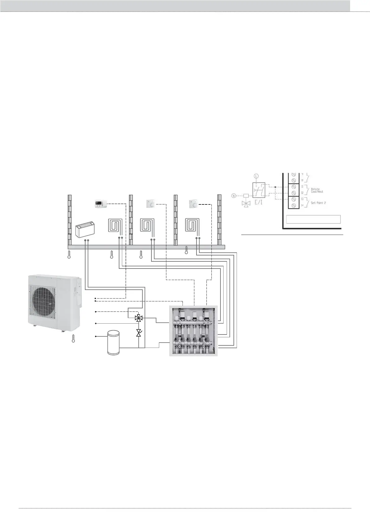
EXAMPLE OF THE SYSTEM WITH ELECTA AND KCTR: heating with underfloor heating and cooling with fan coil
TERMINAL BLOCK
Description
The integrated management of the thermal system and of the heat pump happens by means of an innovative "USER INTERFACE" regulator integrated
WKHUHLQ7KH8VHU,QWHUIDFHLVFRQQHFWHGWRWKHVDPHPDQDJHPHQWLQSXWVRIWKHKHDWSXPSDQGWRDVSHFL¿FHOHFWULFWHUPLQDWLRQERDUG³3&%7(50,1$7
BLOCK”, where the various inputs and outputs of the parts constituting the plant can be connected. The particularity of the USER INTERFACE is made
of a parametric software enabling the customisation of residential comfort, based on the various requirements of rational use of the energy sources and
of the terminal units, for eco sustainability of the entire system. In addition to the normal controls on the mode and state of operation of the heat pump,
all parameters relating to the plant management algorithms can be set using the USER INTERFACE keys. To complete the functions present in the
USER INTERFACE, it is possible to connect the TERMINAL BLOCK with a
KCTR user keyboard (optional accessory), that controls the temperature
and humidity of the main room in the home.
,QDGGLWLRQWRVHWWLQJWKHURRPWHPSHUDWXUHDQGKXPLGLW\E\PHDQVRIWKH.&75WKHXVHUFDQDOVRGH¿QHWKHSHULRGVRIDWWHQXDWLRQRIWKHHQYLURQPHQ-
tal comfort. There is also the possibility of activating the main state and methods of operation of the heat pump and displays available on the USER
INTERFACE.
With the diagram system we want to represent
a classic example of heating by means of ra-
diant panels, and cooling with fan coil. Using
the KCTR installed in the main environment
(1) it is possible to control the activation of the
ELECTA and the head of the radiant panels 1.
With thermostats installed in the other envi-
ronments (2 and 3) it is possible to control the
heads of the respective radiant panels (2 and
3). The 3-way valve must be installed in such a
ZD\WKDWZKHQLWLVQRWSRZHUHGWKHÀRZLVGL-
UHFWHGWRWKHUDGLDQWSDQHOVDQGWKHFRQ¿JXUD-
tion parameter of the mode switching must be
FRQ¿JXUHGWR 7KLVZD\E\SHUIRUPLQJ
the electrical connections to the TERMINAL
BLOCK represented in the image:
- if the contacts remain open one has the he-
ating operation, the 3-way valve sends water
to the radiant collectors and the ELECTA pro-
duces water suitable to radiant systems.
- if the contacts are closed it switches to the
cooling operation, the 3-way valve, powered,
sends water to the fan coil and the ELECTA
produces water that is suitable for fan coil sy-
stems (Set Point 2).
(*) See detail "A"
(*)
A
63
Section I :: User
EN