Temperature sensors electrical characteristics
[table 1] Defrosting temp. sensor: Mod. 105
Outdoor temp. sensor: Mod. 105 - 110
Intake temp. sensor: Mod. 105
Water output and return temp. sensor:
Mod. 105 and 116
Temp. (°C) 5HVLVWDQFHNȍ
031
524
10 19
15 15
20 12
25 10
30 8
35 6.7
40 5.5
45 4.6
50 3.8
55 3.2
[table 2] Compressor drain temp. sensor: Mod. 105
Temp. (°C) 5HVLVWDQFHNȍ
10 1,000
20 600
35 300
40 250
50 160
80 50
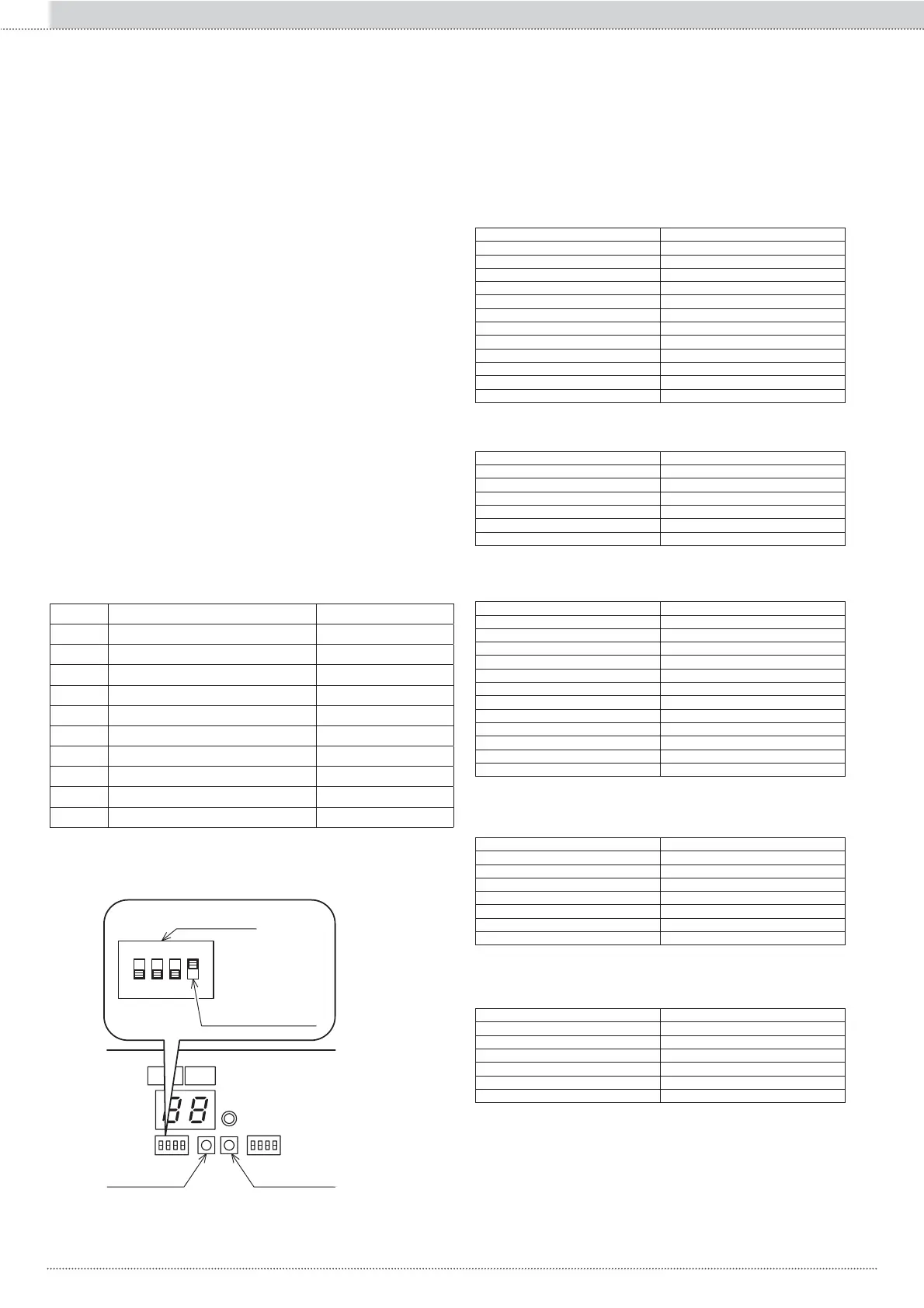
View the log of errors on the PCB DISPLAY
Display method
Press and hold down PUMP SW. and RESET SW. simultaneously for
¿YHVHFRQGVWRGLVSOD\WKHFRGHVDQGQXPEHUVLQWKHVHTXHQFHRIWKH
previous errors.
The PUMP SW button can be used to scroll through the codes of the
previous errors up to a maximum of 8.
(if there are no error codes, the display shows "- -")
Deleting the displayed values
While displaying an error code, press and hold down PUMP SW. and
5(6(76:VLPXOWDQHRXVO\IRU¿YHVHFRQGVWR
switch the display off.
Alternatively, if no operation is implemented for 5 minutes, the display is
switched off automatically.
While displaying an error code, press and hold down the RESET SW but-
ton for at least 10 seconds to delete all the previous errors. “ - - ” appears
on the display.
Viewing the data on the display
1. Set the MODE SW 4 selector from the PCB board (DISPLAY) of the
unit to ON.
The number and the corresponding value are displayed alternately.
2. Press PUMP SW.
Each time you press PUMP SW, the display switches to the sequence
shown below.
6HWWKH02'(6:VHOHFWRUWR2))DIWHUFRPSOHWLQJWKHYHUL¿FDWLRQ
Monitor Monitor screen data contents
d0 Circulation water return temperature 1°C units
d1 Operating frequency of the compressor 1Hz units
d2 Compressor drain temperature 1°C units
d3 Current consumption value 100W units
d4 Fan rpm 10 rpm units
d5 Defrost temperature 1°C units
d6 Outdoor temperature 1°C units
d7
Pump rpm
100 rpm units
d8 Compressor intake temperature 1°C units
d9 Water circulation output temperature 1°C units
[table 3] Defrosting temp. sensor: Mod. 110 - 116
Intake temp. sensor: Mod. 110 - 116
Temp. (°C) 5HVLVWDQFHNȍ
029
523
10 19
15 15
20 12
25 10
30 8.3
35 6.9
40 5.7
45 4.8
50 4.1
55 3.4
[table 4] Water output temp. sensor: Mod. 110
Water return temp. sensor: Mod. 110
Temp. (°C) 5HVLVWDQFHNȍ
025
10 16
20 10
30 7.0
40 4.9
50 3.5
60 2.5
[table 5] Compressor drain temp. sensor:
Mod., 116 and 110
Temp. (°C) 5HVLVWDQFHNȍ
0 100
10 64
35 33
40 27
50 18
80 6.4
ON
4
3
2
1
OFF
Reset SW
Selector
MODE SW 4
Pump SW
110
Section II :: Installation and maintenanceEN