1.2 PLANT ENGINEERING REQUIREMENTS
1.3 CONNECTIONS TO THE TERMINAL BLOCK PCB
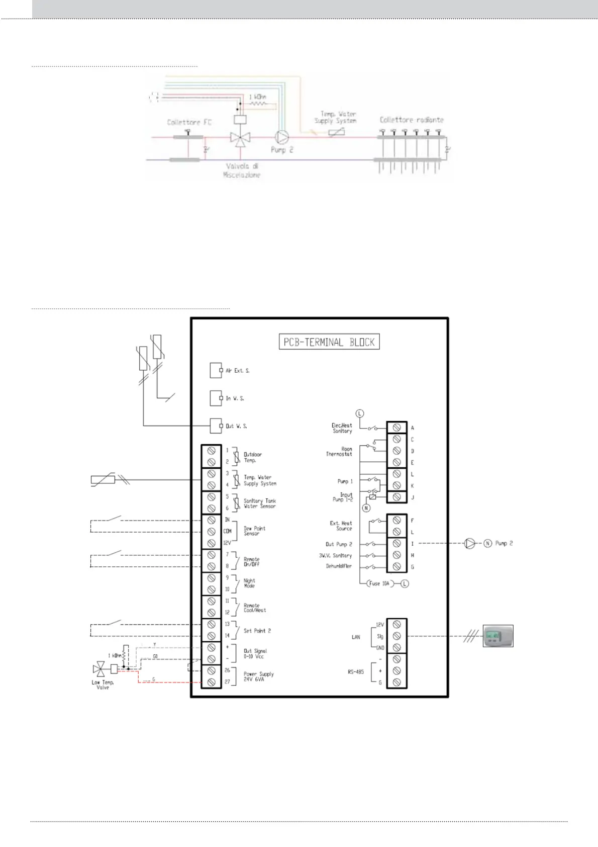
Fig. 3: Positions of the three essential parts in the system, to simultaneously control a high temperature collector and a low temperature one (mixing
valve, pump and temperature probe).
Fig. 4: Essential connections for the simultaneous control of a radiant system and a fancoil one
NOTE: The KCTR is not essential, and to start up ELECTA it can be replaced by a switch that either short circuits the L-K terminals or that switches
the terminal block phase to terminal J.
1. Place the mixing valve between the high and low temperature collectors, so that the water sent to the low temp. Collector is a mixture of its own
return water and the water from the high temp. collector.
2. 6HWXSDNȍUHVLVWRULQSDUDOOHOEHWZHHQWKH*DQG<ZLUHV7KLVUHVLVWRUPXVWEHVHWXSDVFORVHDVSRVVLEOHWRWKH0L[LQJYDOYHWRDYRLGDQ\
signal interference.
3. Set up a pump downstream to the Mixing valve.
4. 3ODFHDNȍWHPSHUDWXUHVHQVRUDW&DWWKHLQOHWRIWKHORZWHPS&ROOHFWRU
NOTE: Maximum length of 30m.
296
Enclosed documentsEN