Rockwell Automation Publication 1715-UM001J-EN-P - December 2020 191
Chapter 6 Configure the Redundant I/O System
4. Click OK.
5. Click the Connection tab, see page 169
.
6. Click the Module Info A tab, see page 170
.
7. Click the Module Info B tab, see page 171
.
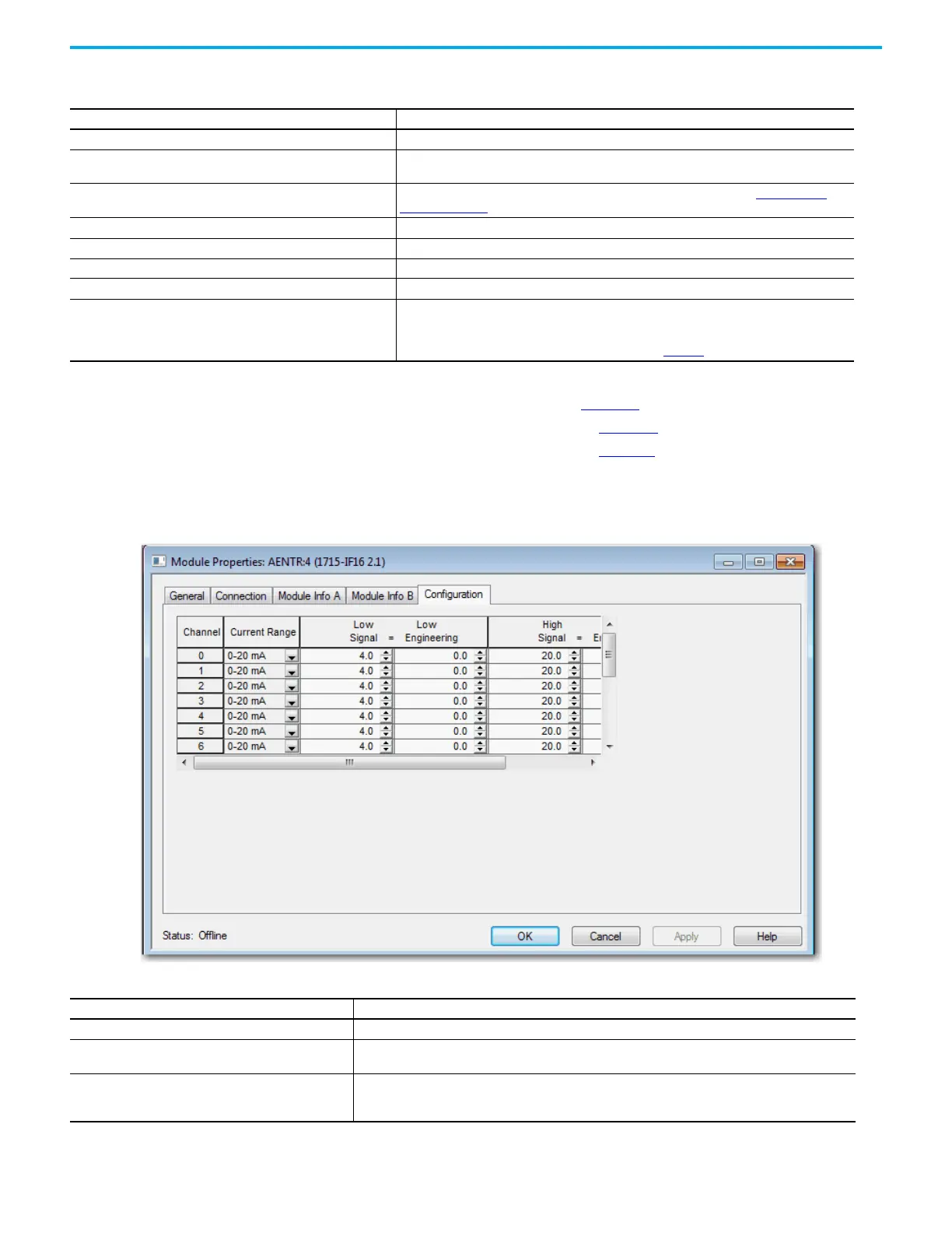
8. Click the Configuration tab.
The Configuration tab appears.
Table 34 - Module Definition Parameters for Analog Input Module
Parameters Description
Series Choose the Series of the module.
Revision
Choose the Revision of the module.
For SIL 2 application choose version 3.01.07 or later for 1715 I/O modules.
Electronic Keying
Choose the Electronic Keying that you wish to use for the selected module. See
Electronic
Keying on page 118.
Connection Leave as ‘Data’ - Listen Only is not supported.
Input Data Display Only.
Data Format Display Only.
Redundant Yes indicates Duplex mode.
SIL 2 Safety
Choose No if SIL 2 operation is not required.
Choose Yes to enable SIL 2 operation. The safety pull-down menu appears only if using Add-on
Profile version 2.01.007 or later. Two new tabs are available for SIL 2 configuration if you
choose Yes. For information on SIL 2 configuration, see Chapter
.
Table 35 - Configuration Parameters for the Analog Input Duplex Module
Parameters Description
Channel Click the channel number to configure parameters for the specified channel (0…15).
Current Range
Displays the current range (0…20 mA) for the channel.
This field is read-only.
Low Signal
Enter the Low Signal value for the channel (between 0.0…20.0 mA). The default is
4.0 mA. This value must be less than the High Signal value. Low Signal and Low Engineering values are
shown in pairs.
 Loading...


