Rockwell Automation Publication 1715-UM001J-EN-P - December 2020 93
Chapter 2 Installation Instructions
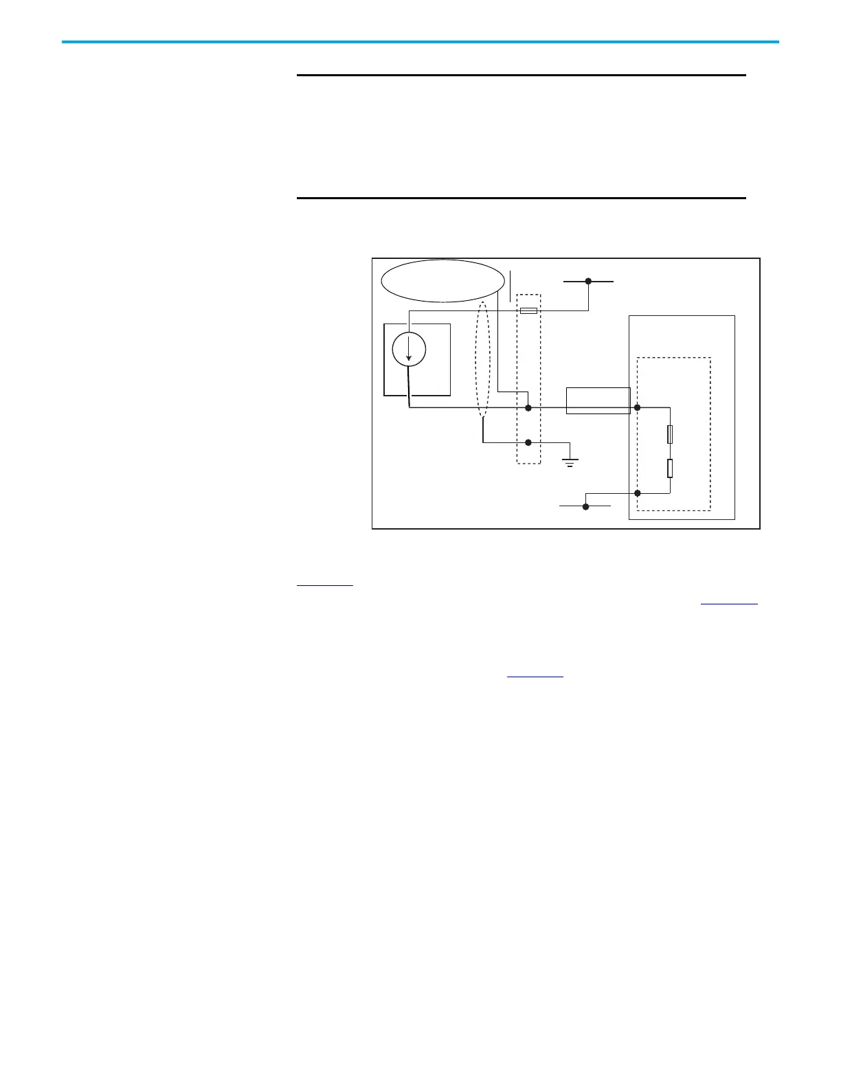
Figure 53 - Connections for 120 Ω Resistor & Secondary Master
Figure 53 above shows the addition of the 120 Ω resistor and HART Secondary
Master to the Two-wire Analog Input Field Loop Circuit shown in Figure 46
.
The above circuit can be accomplished by connecting the secondary Master
and 120
Ω resistor assembly to the 0 V terminal and required channel terminal
on the terminal block as shown in Figure 54
below.
IMPORTANT
It is the responsibility of the Installation Engineer to ensure that
the HART secondary Master is correctly installed. information
regarding HART equipment may be obtained from the HART
website.
http://en.hartcomm.org/
http://en.hartcomm.org/hcp/tech/aboutprotocol/
aboutprotocol_how.html
Shield
Required
Terminal
Blocks
OV
Termination
Assembly
+24V DC
4…20 mA
2-Wire Analog Input
50 mA
120Ω
HART
Secondary Master
120 Ω
 Loading...


