Rockwell Automation Publication 5032-UM001A-EN-P - April 2023 109
Appendix D
Module Diagnostic Assembly
Create User-defined
Diagnostic Assembly Types
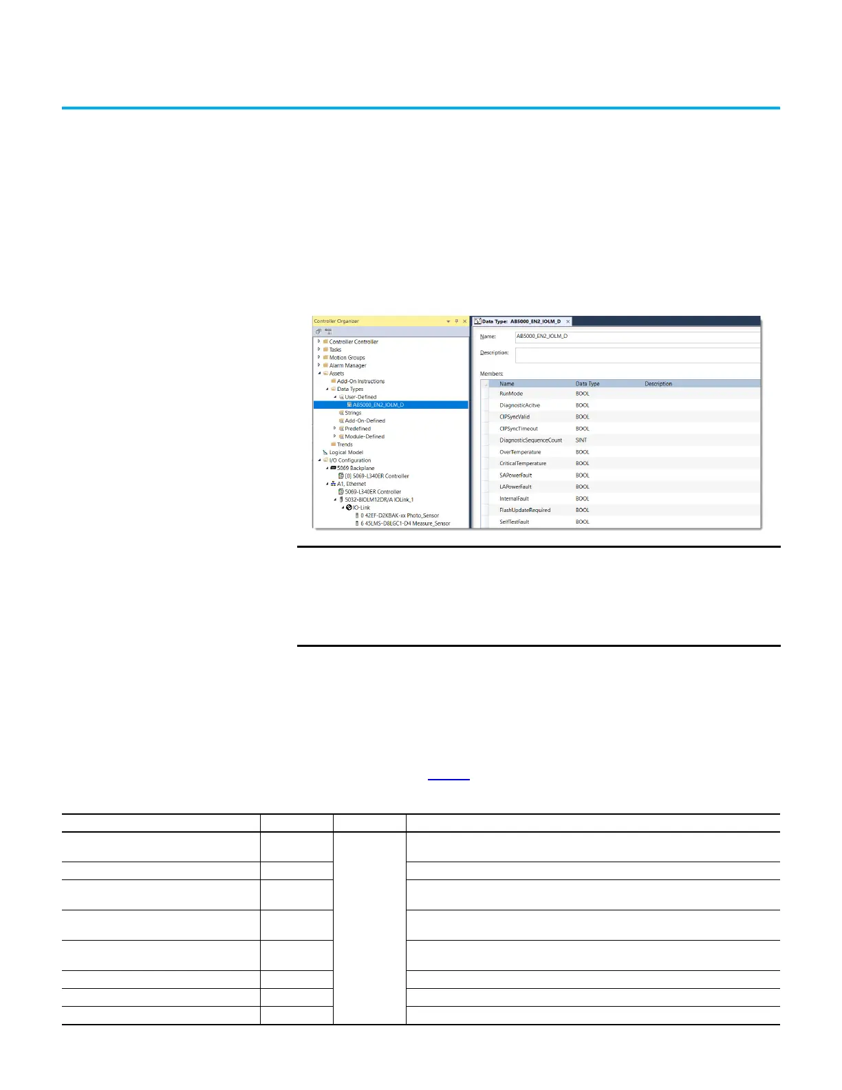
You can use the Studio 5000 Logix Designer application to create user-defined Diagnostic
Assembly types for the ArmorBlock IO-Link master module.
Diagnostic Assemblies
1. Diagnostic IO-Link Master 2 Port Ethernet Assembly
- Instance ID = 0x8007 (32,775)
- Size = 104 bytes
Follow the information in Table 37
to add each member.
IMPORTANT The members that are indicated in the tables are arranged according to
the Data Alignment Rules of controllers. Strictly follow the Data Type
and sequence of the members that are indicated in the tables of this
Appendix. Data misalignment after executing ‘Get Attribute Single’
Message (MSG) instruction may occur if the Data Type and sequence are
not followed.
Table 37 - Diagnostic Assembly Instance 32775
Name Data Type Byte Valid Values
RunMode BOOL
1
0 = Idle
1 = Run mode
InfoBits_Pad1 BOOL This member acts as padding to ensure byte alignment. It can be renamed.
DiagnosticActive BOOL
0 = No diagnostics active
1 = One or more diagnostics are active or the prognostics threshold is reached
CIPSyncValid BOOL
0 = Module not synchronized
1 = Module synchronized
CIPSyncTimeout BOOL
0 = A valid time master has not timed out
1 = A valid time master has timed out
InfoBits_Pad5 BOOL This member acts as padding to ensure byte alignment. It can be renamed.
InfoBits_Pad6 BOOL This member acts as padding to ensure byte alignment. It can be renamed.
InfoBits_Pad7 BOOL This member acts as padding to ensure byte alignment. It can be renamed.
 Loading...


