84 Rockwell Automation Publication 5032-UM001A-EN-P - April 2023
Appendix A Troubleshoot Your IO-Link Master Module
Module Fault Information and Diagnostics on Module Info View
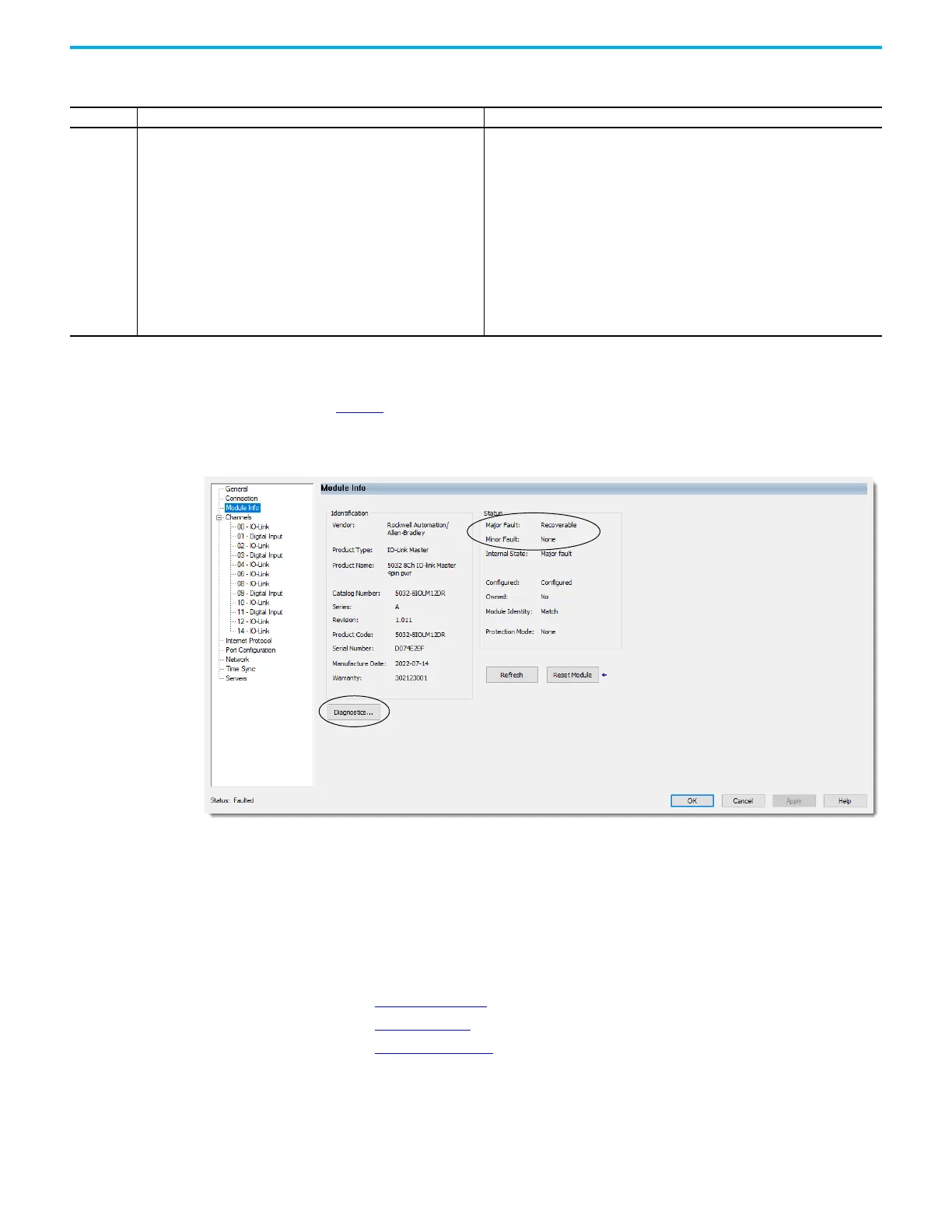
Figure 8 shows where the major and minor fault information, and where to access module
diagnostic information are indicated on the Module Info view.
Figure 8 - Major and Minor Fault Information and Diagnostic
Diagnostics in Studio 5000 Logix Designer Application
You can use diagnostics in the Studio 5000 Logix Designer application to monitor the module
and/or channel operating conditions and to troubleshoot issues that affect a module and/or
channel. You can use diagnostics only when the project is online.
The following are the different diagnostics that you can monitor:
• Module Diagnostics
• Port Diagnostics
• Channel Diagnostics
Table 22 - Special Connection Error Code for IO-Link Master Module
Code Description Recommended Action
16#033A
This error is returned when the connection configuration for an IO-Link
master module tries to enable the auxiliary power of a Class B IO-Link
actuator but the actuator is the regular output operation state.
Complete the following steps:
1. In the IO-Link master Module Properties > General > Module Definition, clear the
IO-Link Class B Enabled checkbox that corresponds to the channel that the Class
B IO-Link actuator is connected to and select OK.
2. In the IO-Link master Module Properties > XX - IO-Link view, select the Disable
Channel checkbox and select Apply to send the configuration to the IO-Link
master module.
You should see the module connection status as ‘Running’.
3. In the IO-Link master Module Properties > General > Module Definition, select the
IO-Link Class B Enabled checkbox that corresponds to the channel that the Class
B IO-Link actuator is connected to and select OK.
4. In the IO-Link master Module Properties > XX - IO-Link view, clear the Disable
Channel checkbox and select Apply to send the configuration to the IO-Link
master module.
 Loading...


