26 Rockwell Automation Publication 5032-UM001A-EN-P - April 2023
Chapter 3 I/O Channel Features
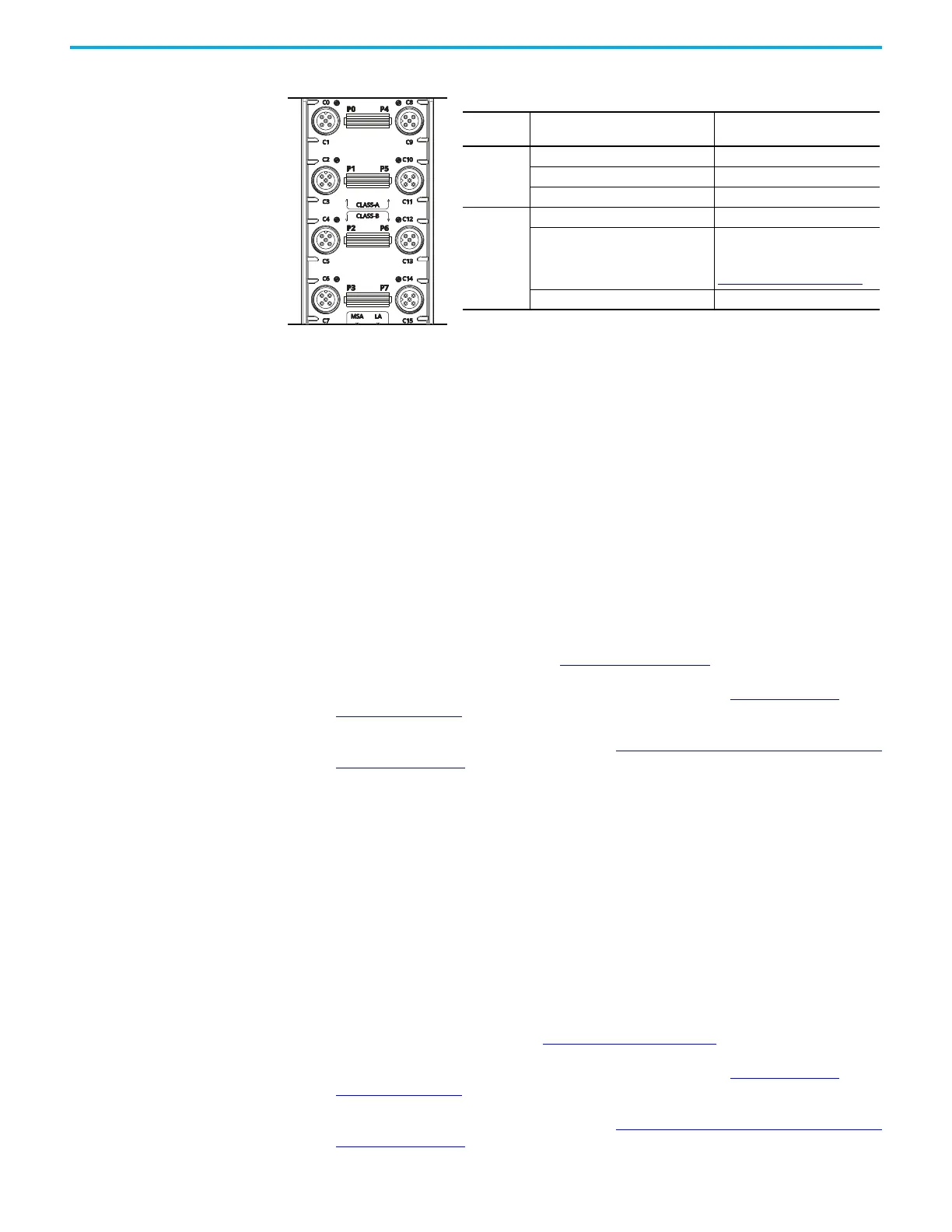
Figure 2 - Short Circuit Protection for Output Channels
When a short circuit condition is detected, the following occurs:
• The channel limits the output current and monitors for the short circuit condition to be
removed.
• The I/O status indicator for the channel flashes red.
•The I.IOLinkxx.Fault or I.Ptxx.Fault tag is set to 1.
Check the channel diagnostic or retrieve the information from the diagnostic assembly
to verify that the short circuit condition is present.
When the short circuit condition is removed, the following occurs:
• The channel restarts in its commanded state.
• The I/O status indicator for the channel turns back to steady yellow.
•The I.IOLinkxx.Fault or I.Ptxx.Fault tag is reset to 0.
Check the channel diagnostic or retrieve the information from the diagnostic assembly
to verify that the short circuit condition is removed.
To check the channel diagnostics, see Channels View
on page 49.
For more information on how to retrieve diagnostic assemblies, see Module Diagnostic
Assembly on page 109.
For more information on using module tags, see IO-Link Master Module and IO-Link Device Tag
Definitions on page 97.
Group Short Circuit
When one of the Group Short Circuit channels experiences a short circuit condition, the other
three channels experience a momentary fault and the fault bit automatically clears.
No Load Diagnostics No Load Diagnostics detects when a signal wire is disconnected from an output channel. When
the I.Ptxxx.Fault tag is set to 1, check the channel diagnostic or retrieve the information from
the diagnostic assembly to verify that the No Load condition is present.
You can only configure channels 1, 3, 9, and 11 as “Digital Output, Short Circuit, No Load
Diagnostics”.
To enable No Load Diagnostics, see XX - Digital Output
on page 52.
For more information on how to retrieve diagnostic assemblies, see Module Diagnostic
Assembly on page 109.
For more information on using module tags, see IO-Link Master Module and IO-Link Device Tag
Definitions on page 97.
Ports
Short Circuit Conditions
with Protection
Description
0, 1, 4, 5
SA Power Short Circuit Short between pins 1 and 3
Odd Channel Output Short Circuit Short between pins 2 and 3
Even Channel Output Short Circuit Short between pins 4 and 3
2, 3, 6, 7
SA Power Short Circuit Short between pins 1 and 3
Odd Channel Output Short Circuit/
LA Power Short Circuit
Short between pins 2 and 5
Group Short Circuit
For more information, see
Group Short Circuit
on page 26.
Even Channel Output Short Circuit Short between pins 4 and 3
 Loading...


