80 Rockwell Automation Publication 5032-UM001A-EN-P - April 2023
Appendix A Troubleshoot Your IO-Link Master Module
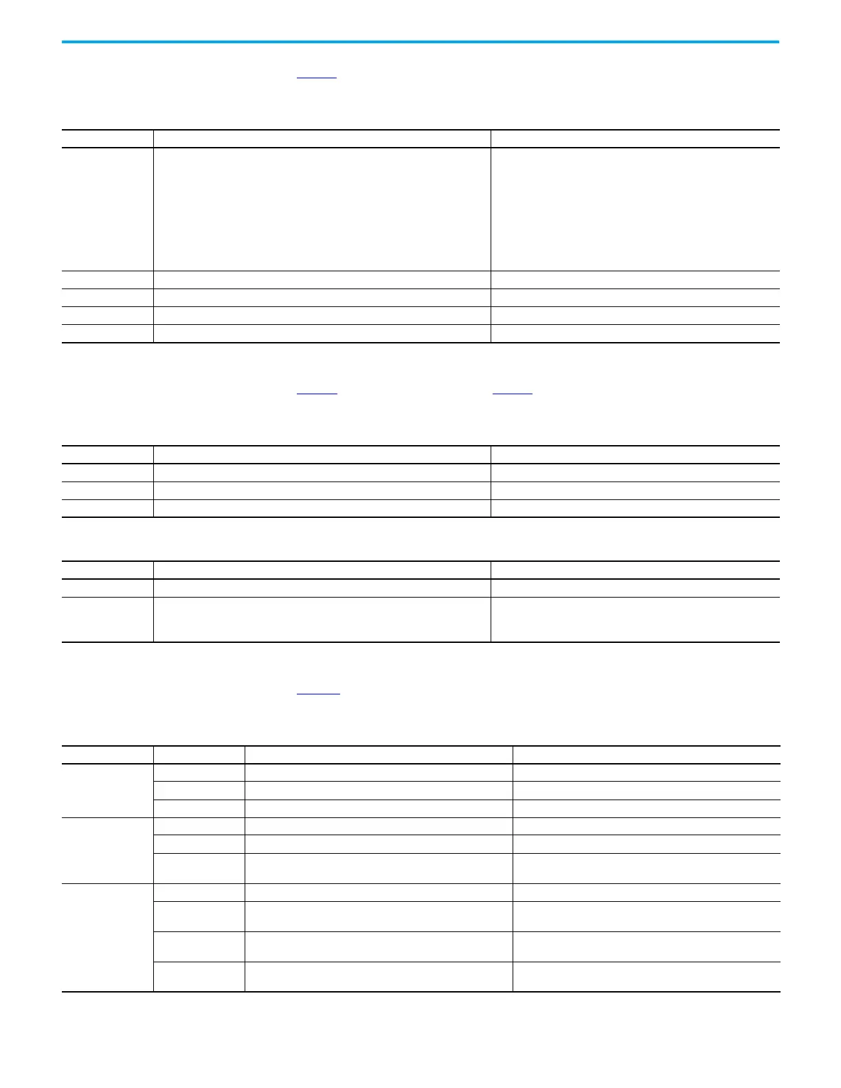
Link Status Indicator Table 17 describes the link status indicator for the ArmorBlock 5000 8-channel IO-Link master
module.
Power Status Indicator Table 18 describes the MSA power and Table 19 describes the LA power status indicator for the
ArmorBlock 5000 IO-Link master module.
Channel Status Indicator Table 20 describes the channel status indicator for the ArmorBlock 5000 IO-Link master
module.
Table 17 - Link 1 and Link 2 Status Indicator
Indicator State Description Recommended Action
Off
One of the following conditions exists:
• The module is not powered.
• The Ethernet cables are not properly seated in the module and connected
devices.
• No link has been established.
• The port is administratively disabled.
• The port configuration is configured in a manner that can result in issues.
For example, the port can be configured to Autonegotiate and the port at the
other end of the cable is configured such that Autonegotiate is disabled.
Complete one of the following:
• Apply power as necessary.
• Verify that the cables are properly seated in the module and
connected devices.
• Check if the port is disabled in the Studio 5000 Logix Designer
application and confirm if that is the desired state.
• Check the configuration for the links at both ends of the cable
and verify that they are correct to perform normal operations.
Steady green Link has been established on the indicated port at 100 Mbps. None
Flashing green Link activity exists on the indicated port at 100 Mbps. None
Steady yellow Link is established on the indicated port at 10 Mbps. None
Flashing yellow Link activity exists on the indicated port at 10 Mbps. None
Table 18 - MSA Power Status Indicator
Indicator State Description Recommended Action
Off There is no MSA power. Apply power as necessary.
Steady green MSA power is within the valid range of 18…30V. None
Flashing red MSA power is outside the valid range of 18…30V. Verify that the power supply meets the module specifications.
Table 19 - LA Power Status Indicator
Indicator State Description Recommended Action
Steady green LA power is within valid range of 18…30V. None
Flashing red
One of the following conditions exists:
• There is no LA power.
• LA power is outside the valid range of 18…30V.
Complete one of the following:
• Apply power as necessary.
• Verify that the power supply meets the module specifications.
Table 20 - Channel Status Indicator
Channel Mode Indicator State Description Recommended Action
DI
Off The input is off. None
Steady yellow The input is on. None
Flashing red Short circuit condition or SA power on the port is faulted. Correct the short circuit condition or SA power fault.
DO
Off The output is off. None
Steady yellow The output is on. None
Flashing red
No Load (if No Load Diagnostic is enabled) or output short
circuit condition exists, or power on the port is faulted.
Correct the No Load or output short circuit condition, or power
fault.
IO-Link
Off Not applicable None
Steady yellow
IO-Link communication is established between the IO-Link
master module and IO-Link device.
None
Flashing yellow
No IO-Link device is attached to the port or IO-Link
communication is not established.
Disconnect and reconnect the IO-Link device.
Flashing red
CQ line short circuit or short circuit condition exists, or SA
power on the port is faulted.
Correct the CQ line short circuit or short circuit condition, or
SA power fault.
 Loading...


