30 Rockwell Automation Publication 5032-UM001A-EN-P - April 2023
Chapter 4 Common Features of IO-Link Device Integration
Fallback Mode Fallback mode provides the benefits of configuration in IO-Link mode and the same
performance of “Digital Input” or “Digital Input, Timestamp” modes. When a channel is set to a
Fallback mode:
• You can configure the device through the IO-Link interface.
• The device operates in “Digital Input” or “Digital Input, Timestamp” mode.
The device operates in Fallback mode when you configure the channel as “Digital Input,
Fallback” or “Digital Input, Timestamp, Fallback”.
You can easily switch the device to digital input mode for operation by uninhibiting the device,
or switch to IO-Link mode for configuration by inhibiting the device.
When the device is used in Fallback mode, no input tag or output tag is generated for the
device connection. Input data is available in the input tag of the IO-Link master module for
that channel – name:I:Ptxx, where xx is the channel number.
For example, if the device is attached to Port 2 (Ch04 for pin 4) and the channel mode is set to
“Digital Input, Fallback” or “Digital Input, Timestamp, Fallback”, then input data for the device is
available in the tag IOLM:I:Pt04.
IO-Link Device Connection Every IO-Link device has its own connection to the controller. When an IO-Link device is
attached to a non-Fallback channel, the following data is provided through the connection:
• Input tag – Process data input with time stamp, fault and status reporting,
configuration change detection, and latest IO-Link event from the device
• Output tag – Process data output and reset configuration change
To set the RPI of the connection, see Connection View
on page 69.
Connection Types
IO-Link devices may support multiple sets of process data. Each set of process data is
mapped to a connection type. Input and output tags for each connection type is generated
from their respective set of process data that is defined in the device IODD.
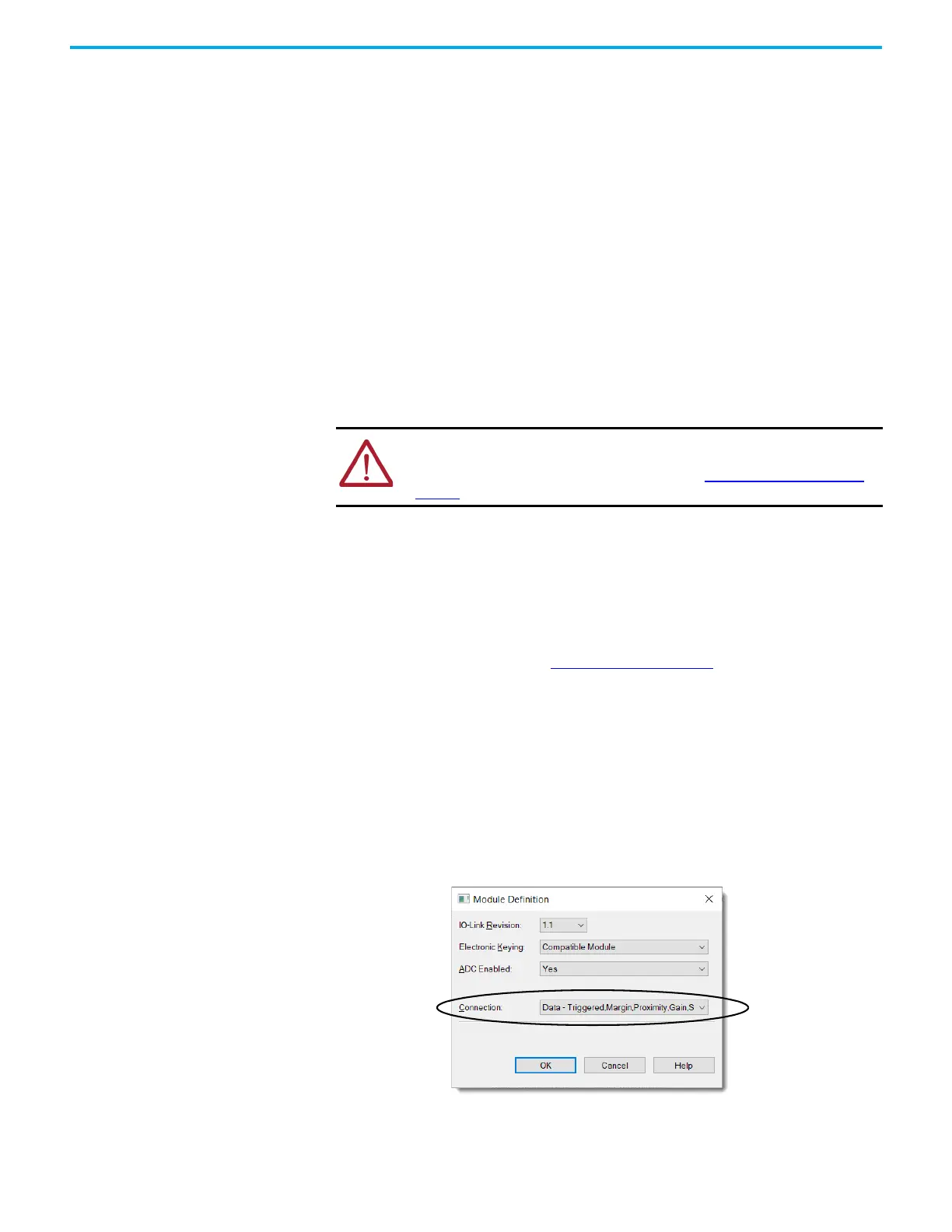
To determine the type of process data that the device provides, select the type of connection
in the Module Definition dialog.
Figure 3 - Select IO-Link Device Connection Type
WARNING: If you replace an IO-Link device without first inhibiting the device, the
device configuration is not synchronized with the project.
For more information on device replacement, see Replace IO-Link Devices on
page 73.
 Loading...


