Rockwell Automation Publication 5032-UM001A-EN-P - April 2023 81
Appendix A Troubleshoot Your IO-Link Master Module
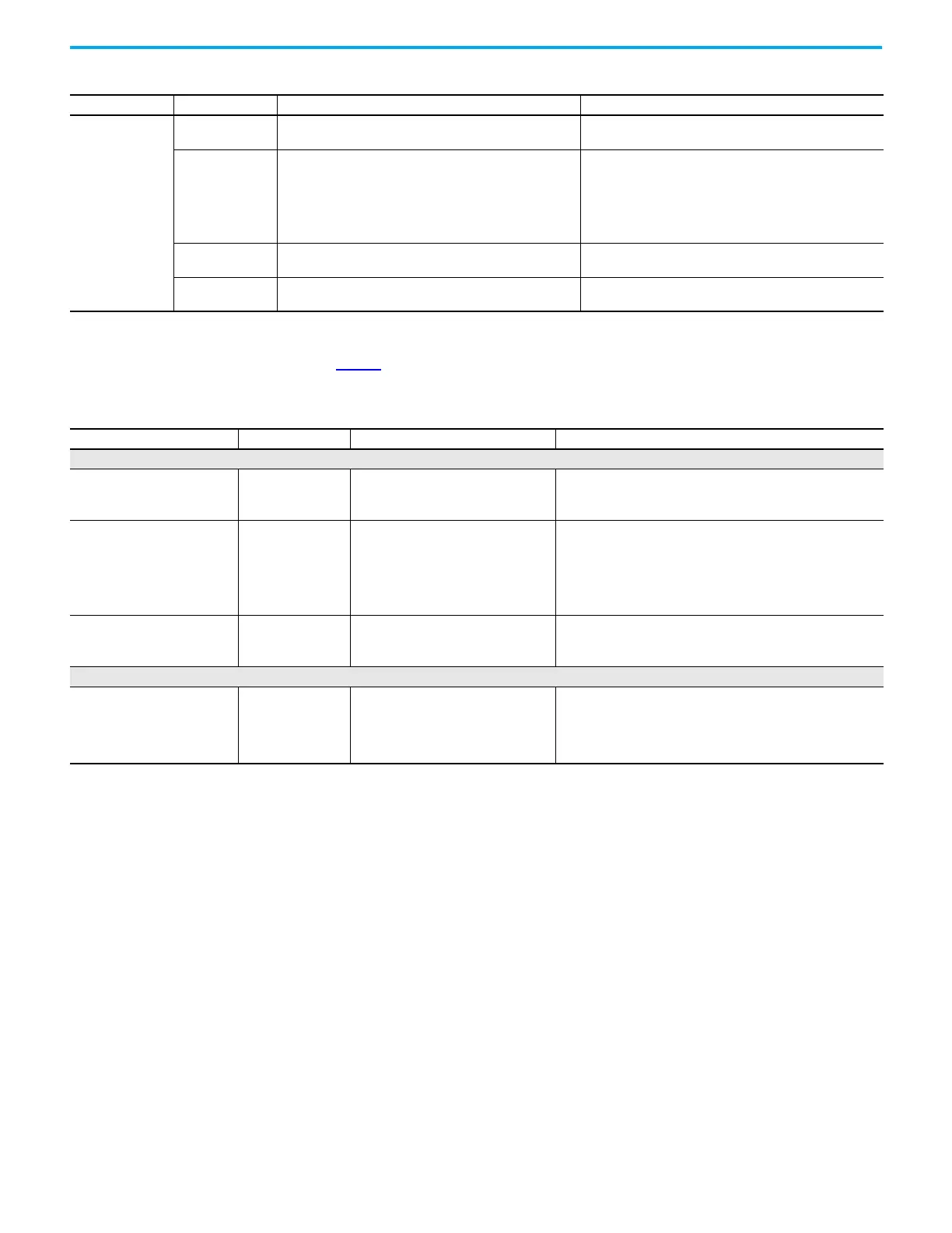
Troubleshoot Wiring Issues Table 21 describes the possible faults that can occur due to incorrect usage or when wiring the
ArmorBlock 5000 8-channel IO-Link master module.
Fallback
Off
The input is off when the device is operating in standard I/O
mode.
None
Steady yellow
One of the following conditions exists:
• The input is on when the device is operating in standard I/O
mode.
• IO-Link communication is established between the IO-Link
master module and device when the device is operating in
IO-Link mode.
None
Flashing yellow
No IO-Link device is attached to the port or IO-Link
communication is not established.
Disconnect and reconnect the IO-Link device.
Flashing red
CQ line short circuit or short circuit condition exists, or SA
power on the port is faulted.
Correct the CQ line short circuit or short circuit condition, or
SA power fault.
Table 20 - Channel Status Indicator (Continued)
Channel Mode Indicator State Description Recommended Action
Table 21 - Possible Faults due to Incorrect Usage or Wiring
System/Function Fault Description Recommended Action
Power Port
POWER IN
Lower/higher voltage
input used.
Module unable to operate. Next module in
daisy chain unable to operate.
Complete the following steps:
1. Verify that the system is powered.
2. Verify that the POWER Input is within the operating voltage range.
POWER OUT
Used to provide power to another
daisy chained module as input to
POWER IN.
Unable to provide
enough power.
Module unable to operate. Next module in
daisy chain unable to operate.
Complete the following steps:
1. Verify that the system is powered.
2. Verify that all modules in the daisy chain receive sufficient
power.
3. Verify that the power passing through the daisy chain is within
the specifications of the module.
POWER IN
Reversed polarized
power input used.
Module unable to power up. No damage is
caused to module.
Complete the following steps:
1. Verify that the system is powered.
2. Verify that the power cable wiring is installed properly.
I/O Port
Configurable I/O
Configured as output
but wired as input.
Two operating
outputs are joined.
Module operates. However, a fault is
reported if excess current is drawn from
the module due to the difference in
potentials and the affected channel
switches off.
Complete the following steps:
1. Verify that the cable is installed properly.
2. Check the channel status indicators. If the indicator is showing
flashing red, confirm that the I/O cable is installed properly.
 Loading...


