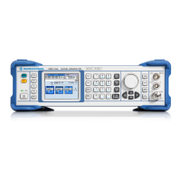
Example of Setup R&S SMB
1407.0812.62 2.4 E-2
Example of Setup
A central element of the R&S SMB display is the block diagram that illustrates the signal flow. Each
block represents a section of signal generation. The main settings of a block are indicated in the block.
The interconnection of employed inputs and outputs is also shown. The user is thus always informed
about the connection of inputs and outputs in the signal flow and where they can be configured.
A window is opened for each menu where parameters can be set. All open menus are of equal priority
(not modal) and can be accessed any time.
The R&S SMB can be entirely operated from the front panel. Peripherals such as mouse or keyboard
can be connected but are not essential.
With the aid of the rotary knob, the user can navigate in the block diagram and the dialogs. The cursor
is moved line by line through the block diagram or dialog. Turning the button clockwise advances the
cursor.
The selected block can be activated or deactivated with the
ON/OFF TOGGLE key. Active blocks are
highlighted by a colored background.
Generation of an Amplitude-Modulated Signal
In the example, a simple AM-modulated signal is configured. Proceed as described below:
1. Activate default (preset) state.
2. Select and activate AM modulation.
3. Set frequency and level and activate RF signal.
Step 1: Activate default (preset) state
Set a defined instrument state by pressing the
PRESET
key.

 Loading...