Reference
Modification-No.
- 0 -
Page
25
Date
1996 05 10
Install
914 F
L4
R4
L1
R1
L2
R2
L3
R3
+z
-z
+x
-x
P
ø11mm
40mm
1mm
ø11mm
40m
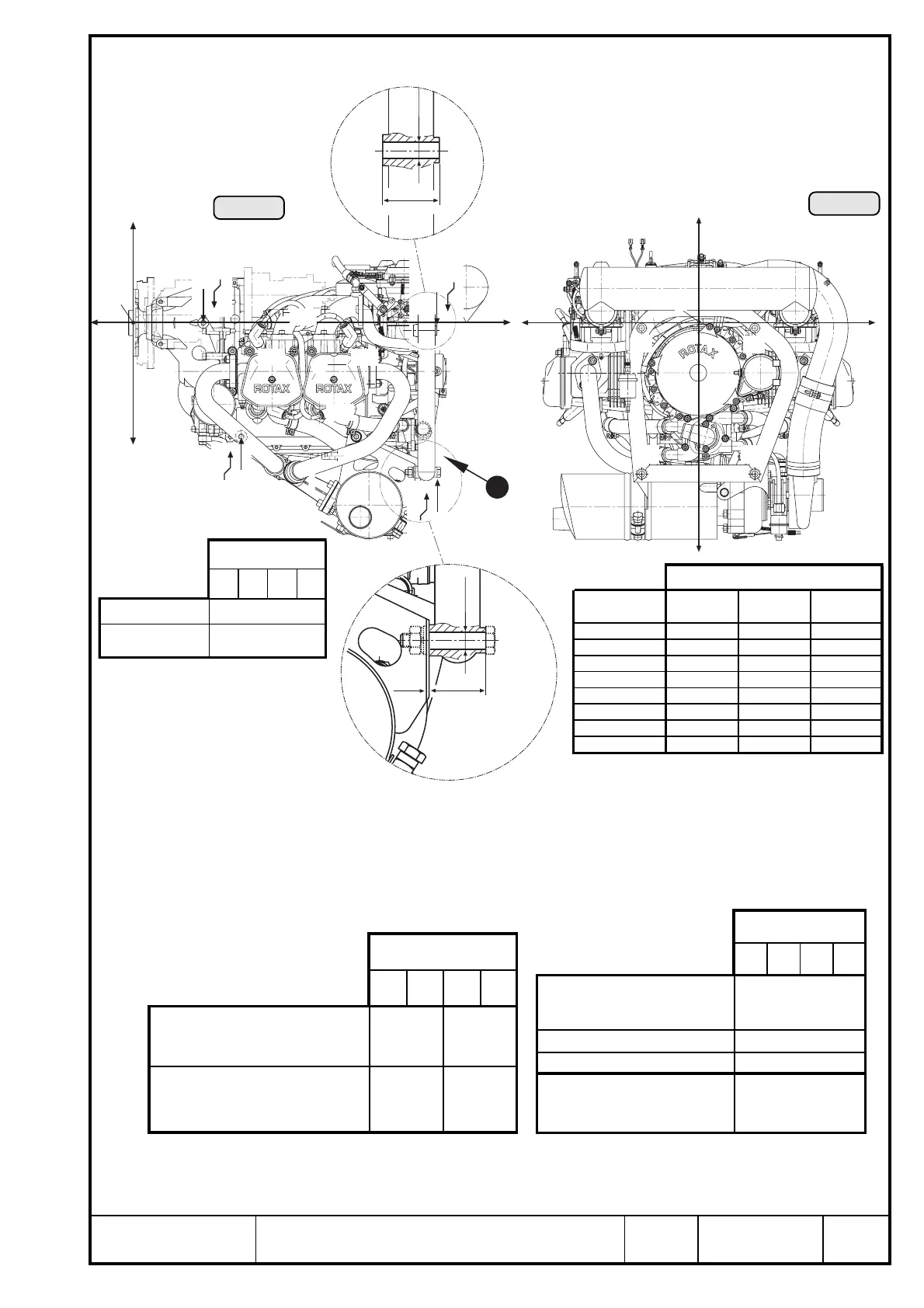
10.1) Definition of attachment points
See Ill. 9/10.
▲ WARNING: The engine suspension to be designed by the aircraft or fuselage
builder such that it will carry safely the maximum occurring opera-
tional loads without exceeding the max. allowable-forces and mo-
ments on the engine attachment points.
Ill. 10
Ill. 9
1
L3
R3
L2
R2
+z
-z
+y
- y
P
Axes
attachment
point
x axis y axis z axis
L1 -200,8 -71,0 -211,0
R1 -200,8 71,0 -211,0
L2 -562,0 105,0 -277,0
R2 -562,0 -105,0 -277,0
L3 -562,0 105,0 -7,0
R3 -562,0 -105,0 -7,0
L4 -130,3 -71,0 0,0
R4 -130,3 71,0 0,0
attachment point
1L 1R 4L 4R
thread size M10
min. length of
thread engagement
25 mm (1")
attachment point
2L 2R 3L 3R
max. allowable forces
(limit load) in (N)
in x axis 5 000
in y axis 2 000
in z axis 3 000
max. allowable bending moment
(limit load) in (Nm)
in x, y and z axis
100
attachment point
1L 1R 4L 4R
max. allowable forces (limit
load) in (N) in x, y and z axis
5000 1900
max. allowable bending moment
(limit load) in (Nm) in x, y
and z axis
77 39
▲ WARNING: Tighten all engine suspension screws as specified by the aircraft
builder.

 Loading...


