Reference
Modification-No.
- 0 -
Page
69
Date
1996 05 10
Install
914 F
14
ø35
ø6
ø30
14
104
ø6
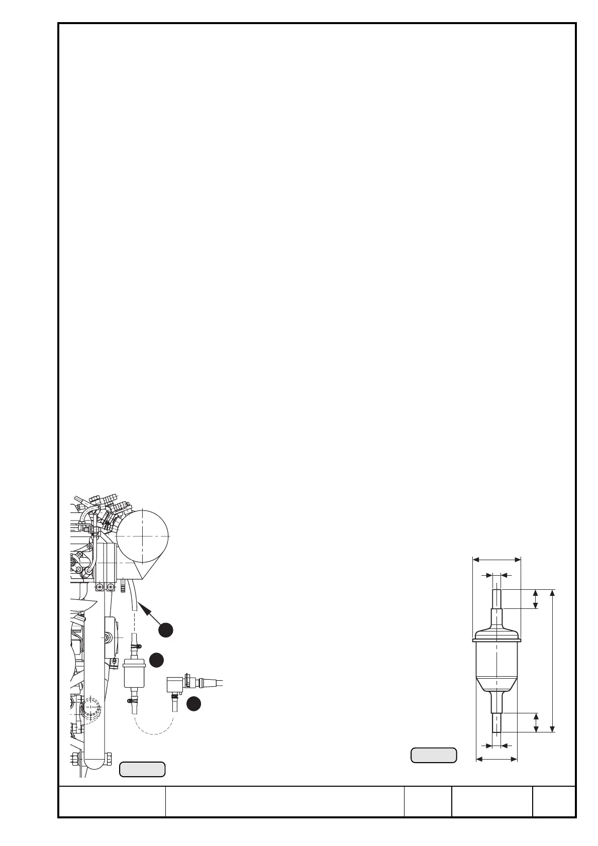
Ill. 48
Ill. 49
2
1
3
17.2) Airbox pressure sensor
See Ill. 47.
➪ effective range: 500 ÷ 2500 hPa
deviation: max. ± 60 hPa
➪ operating temperature: min. - 40° C (- 40° F)
max. +125° C (257° F)
➪ dimensions and attachment: see sketch (Ill. 47)
➪ fitting position:
The pressure connection (Pos. E Ill. 47) points downwards to prevent possible
condensate from entering the sensor, i.e. the longitudinal axis z4 has to be parallel
to z-axis in system of coordinates.
tolerated deviation of parallelism ± 60°
➪ location of installation:
vibration neutralized installation
■ ATTENTION: The pressure connection has to be protected against entering of
foreign matter e.g. oil, fuel, water etc. (see chapter 17.2.1).
◆ NOTE: Location of installation is limited by the length of the wiring harness.
➪ length of cable assy.: approx. 250 mm (10 in) from TCU.
17.2.1) Water trap
See Ill. 48/49.
Water trap is included in the supply volume of the engine.
➪ dimensions and attachment: see sketch (Ill. 49)
➪ location of installation:
The water trap Q has to be installed by clamps free of stress between
hose W 4x7 of airbox and the airbox pressure sensor E.
■ ATTENTION: Utilize full slip-on length on all connections.

 Loading...


