Reference
Modification-No.
- 0 -
Page
68
Date
1996 05 10
Install
914 F
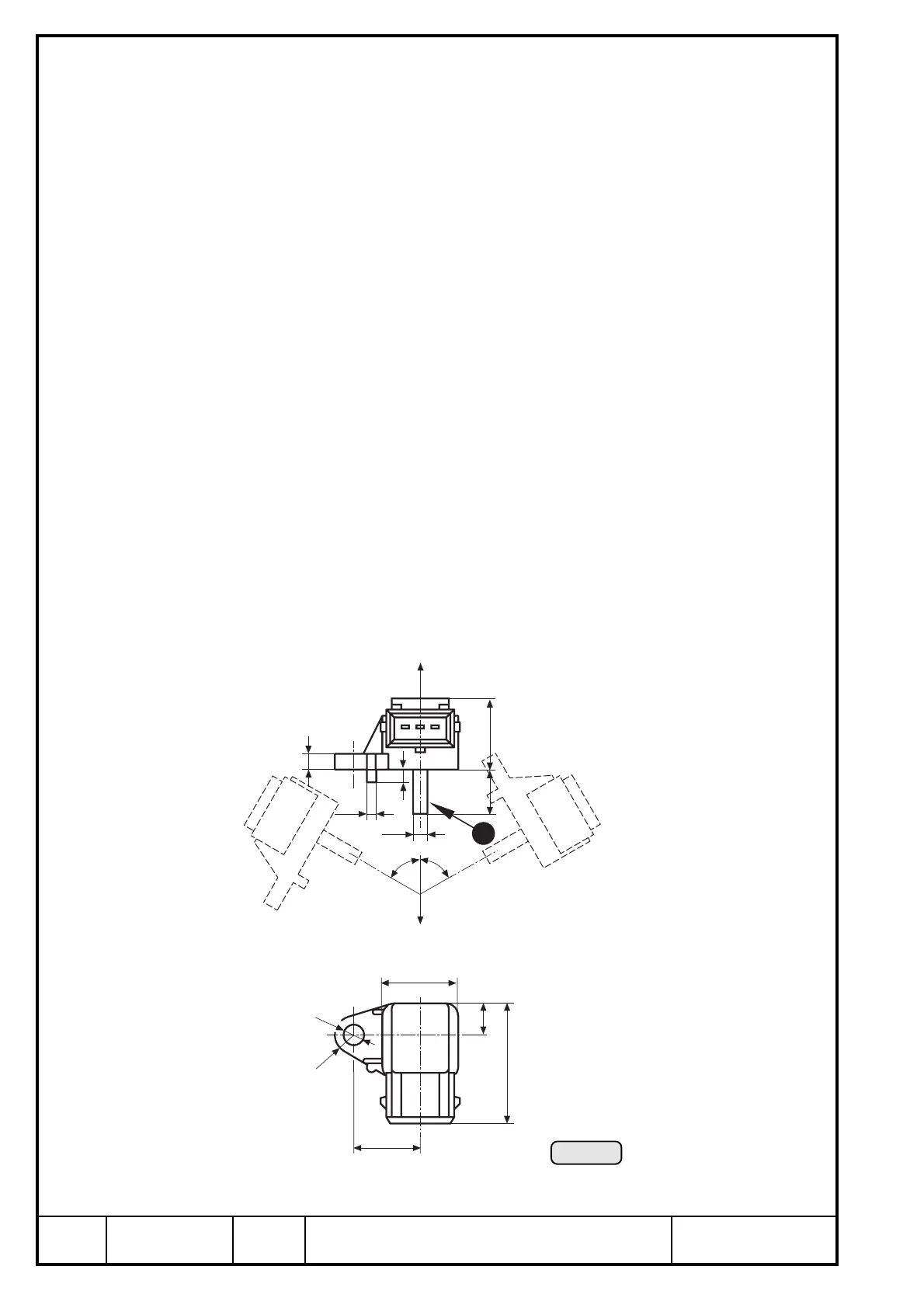
17.1) Static pressure sensor
See Ill. 47.
➪ effective range: 100 ÷ 1200 hPa
deviation: max. ± 40 hPa
➪ operating temperature: min. - 40° C (-40° F)
max. +125° C (257° F)
➪ dimensions and attachment: see sketch (Ill. 47)
➪ fitting position:
The pressure connection (Pos. E Ill. 47) points downwards to prevent possible
condensate from entering the sensor, i.e. the longitudinal axis z4 has to be parallel
to z-axis in system of coordinates.
tolerated deviation of parallelism ± 60°
➪ location of installation:
vibration neutralized installation in a calm zone, e.g. in cockpit.
In the area of the pressure pick-up approx. the same atmospheric pressure (static
air pressure) has to prevail as at inlet of turbo charger.
■ ATTENTION: The pressure connection has to be protected against entering of
foreign matter e.g. oil, fuel, water etc.
◆ NOTE: Location of installation is limited by the length of the wiring harness.
➪ length of cable assy.: approx. 250 mm (10 in) from TCU.
60°
60°
ø3
ø4,7
4
22,5
14
5
+z4
-z4
24
21
10
38
ø6,5
R6
Ill. 47
3

 Loading...


