Reference
Modification-No.
- 0 -
Page
70
Date
1996 05 10
Install
914 F
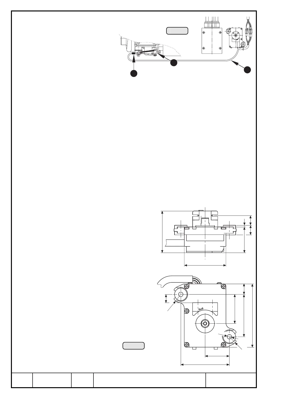
18) Servo motor
See Ill. 50/51.
The correct adjustment of the servo
cable Q and consequently the waste
gate W was made already on the
course of the testrun at ROTAX.
6,5
R12
60
37
60
2,5
14
14
15
61
91
42
12
70
35
R12
Ill. 51
1
2
Ill. 50
3
Prior to engine operation check the position of the waste gate as follows:
▲ WARNING: Engine stop - ignition "OFF".
➪ switch on TCU.
➪ servo motor runs with waste gate closed.
➪ slacken adjustment screw E on servo cable support and turn adjustment screw until waste
gate is completely closed.
➪ proper pretensioning of the servo cable is achieved by turning in the adjustment screw by
one complete rotation.
Additionally, only the actual attaching of the servo motor has to be performed.
➪ operating temperature: min. - 20° C (- 4° F)
max. +60° C (140° F)
➪ dimensions and attachment: see sketch (Ill. 51)
➪ location of installation:
vibration neutralized place
▲ WARNING: Installation in the engine com-
partment is not permitted since
the servo motor is not of a fire
resistant construction.
A recommendable location is in
the cockpit below the instrument
panel.
◆ NOTE: Place of installation is limited by
the length of the servo cable.
➪ cable length: approx. 1000 mm (40") from
waste gate
➪ bending radius: min. 50 mm (2")

 Loading...


