Reference
Modification-No.
- 0 -
Page
95
Date
1996 05 10
Install
914 F
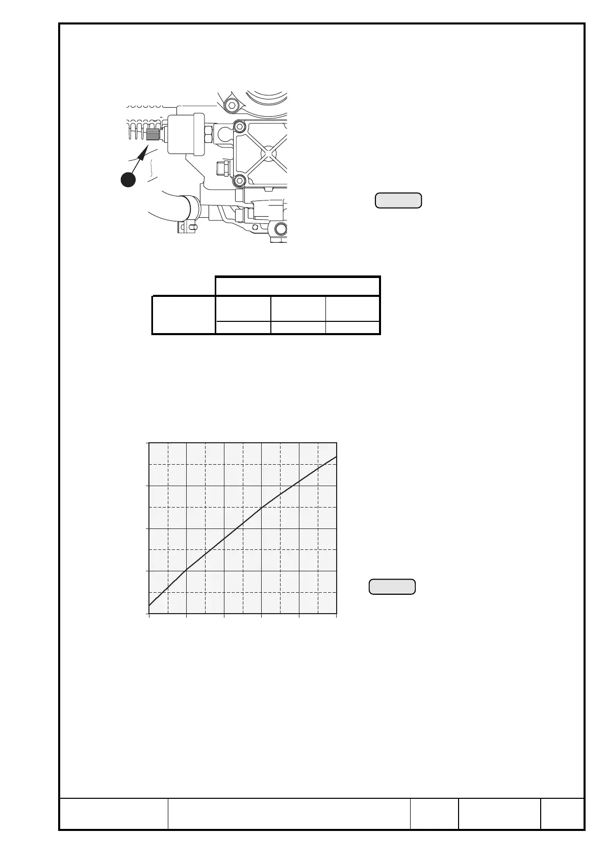
23.3) Oil pressure sensor
See Ill. 75/76.
➪ location: oil pump housing
➪ position of connection on oil pressure pick-up Q:
➪ connection of
pick-up wiring: single pole screw connection for cable eye 3 to DIN 46225
➪ grounding: via engine block
➪ graph of resistance over pressure
Axes
x axis y axis z axis
ca. -100 7 5 ca. -150
point of
connection
200
(bar)
150
100
50
0
108642
(Ω) ohm
Ill. 76
Ill. 75
1
■ ATTENTION: The graph resistance over pressure has been determined, and is
effective at the following conditions only.
ambient temperature: 20° C (68° F)
voltage: 12 V
tolerance: ± 5%
BOMBARDIER-ROTAX offers a non-certified pressure gauge. Refer to current spare
parts list.
▲ WARNING: Certification to the latest requirements such as FAR of JAR has to be
conducted by the aircraft builder.

 Loading...


