Reference
Modification-No.
- 0 -
Page
80
Date
1996 05 10
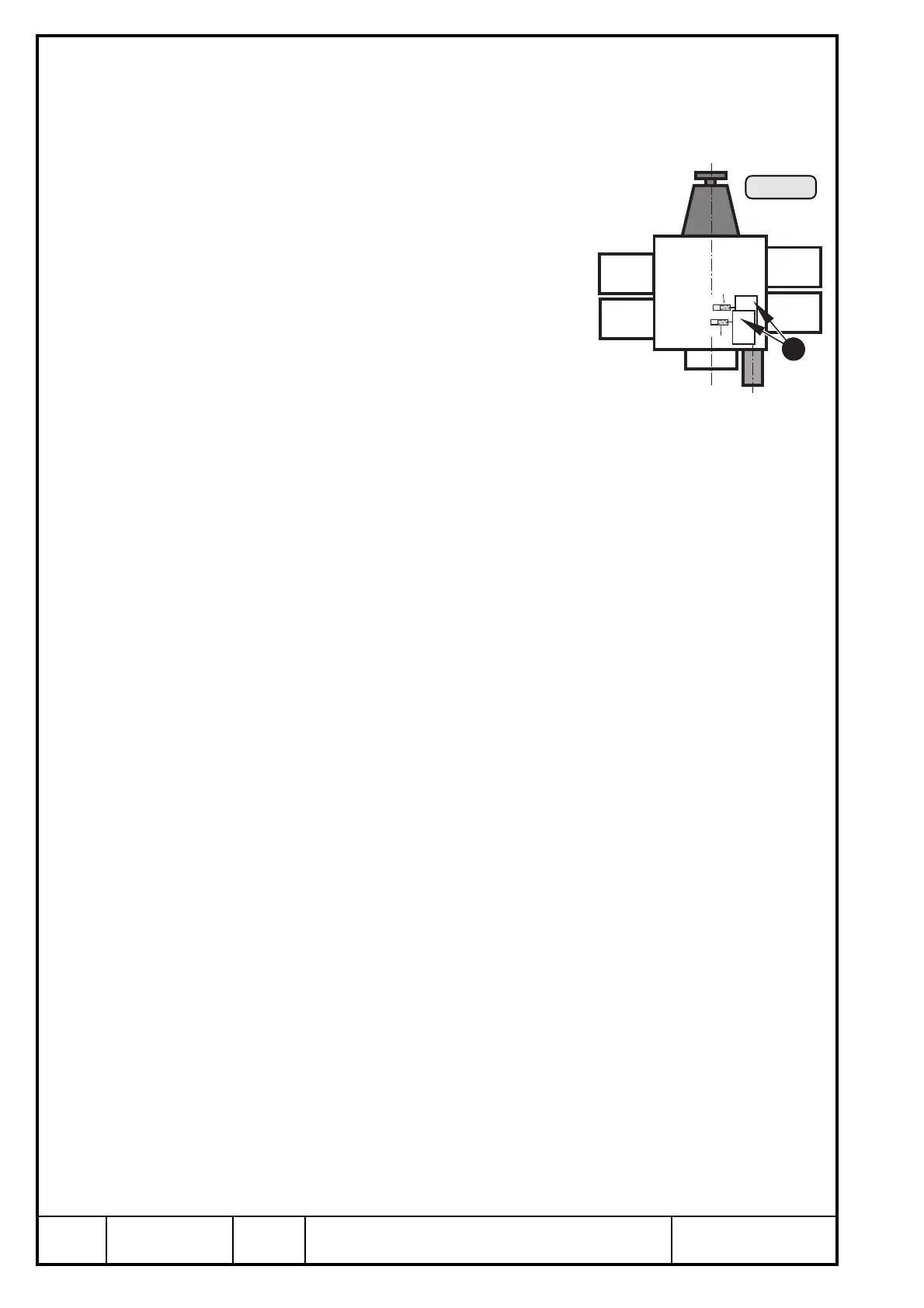
Install
914 F
br
br
B
A
Cyl. 1
Cyl. 3
Cyl. 2
Cyl. 4
19.4.3) Electronic modules
See Ill. 4/58.
Ambient temp. for the electronic modules Q: ............. max. 80°C (176°F).
19.4.4) Ignition switches (on-off switch)
See Ill. 58.
➪ type: two separate, suitable on-off switches
(Ill. 52, pos. L)
➪ switching voltage:min. 250 V
➪ switching current: min. 0,5 A
Feeding lines to on-off switches on the electronic
module (see Ill. 58).
➪ 1 each flexible cable 0,75 mm
2
, brown
length approx. 35 mm (1 3/8") beginning at electronic module with one
each plug socket and insulating sleeve 3,96 mm.
◆ NOTE: One each plug and insulating sleeve are supplied loosely
packed.
➪ shorting cable of top electronic module (marked "A") for ignition circuit A.
Shorting cable of bottom electronic module (marked "B") for ignition circuit
B.
◆ NOTE: Ignition circuit A controls: top spark plugs of cylinders
Ignition circuit B controls: lower spark plugs of cylinders
■ ATTENTION: The electromagnetic compatibility (EMC) and electromag-
netic interference (EMI) depends essentially on the shorting
cables used.
Min. section area: 2x 0,75 mm
2
(shielded flexible cable,
shielding braid on both ends grounded).
■ ATTENTION: The metal base of each ignition switch must be grounded to
air craft frame.
Ill. 58
1

 Loading...


