Reference
Modification-No.
- 0 -
Page
44
Date
1996 05 10
Install
914 F
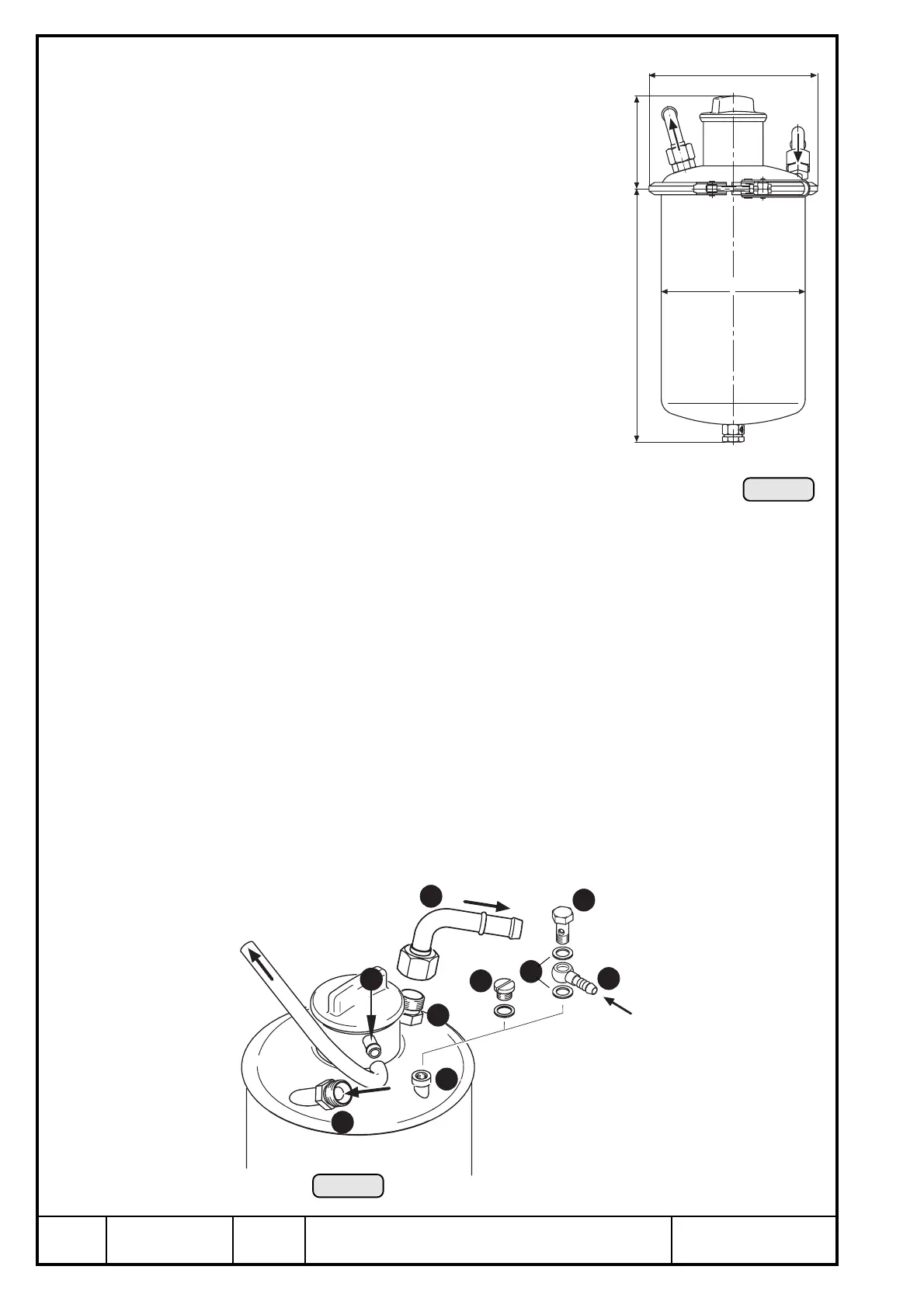
13.4.3) Oil tank
See ill. 27/28.
The oil tank is furnished with 2 screw connections
M18x1,5 and with a tapped hole (M10x1).
Connections for oil circuit (engine)
Oil inlet Y and outlet U via standard swivel joint
and connecting bend I.
2x connecting bend 90° I
outside dia. 12 mm (0,47 in.)
slip-on length max. 24 mm (0,94 in.)
tightening torque 25 Nm (220 in.lb)
1x venting nipple O
outside dia..................... 8 mm (0,31 in.)
slip-on length................. max. 15 mm (.59 in.)
Connection for oil circuit (turbo charger)
ø165
90
248
ø139,2
Ill. 27
hose nipple P 4/6 DIN 7642
outside dia. 8 mm
slip-on length max. 20 mm
tightening torque of the banjo bolt { M10x1x19: 17 Nm (150 in.lb)
◆ NOTE: In the standard supply volume the connection } is closed
by the plug screw q.
This screw plug has to be removed and is replaced by the hose nipple P,
sealing ring w 10x14 DIN 7603 and banjo bolt {.
Ill. 28
13
11
6
8
7
9
12
14
10

 Loading...


